- English
- Español
- Português
- русский
- Français
- 日本語
- Deutsch
- tiếng Việt
- Italiano
- Nederlands
- ภาษาไทย
- Polski
- 한국어
- Svenska
- magyar
- Malay
- বাংলা ভাষার
- Dansk
- Suomi
- हिन्दी
- Pilipino
- Türkçe
- Gaeilge
- العربية
- Indonesia
- Norsk
- تمل
- český
- ελληνικά
- український
- Javanese
- فارسی
- தமிழ்
- తెలుగు
- नेपाली
- Burmese
- български
- ລາວ
- Latine
- Қазақша
- Euskal
- Azərbaycan
- Slovenský jazyk
- Македонски
- Lietuvos
- Eesti Keel
- Română
- Slovenski
- मराठी
- Srpski језик

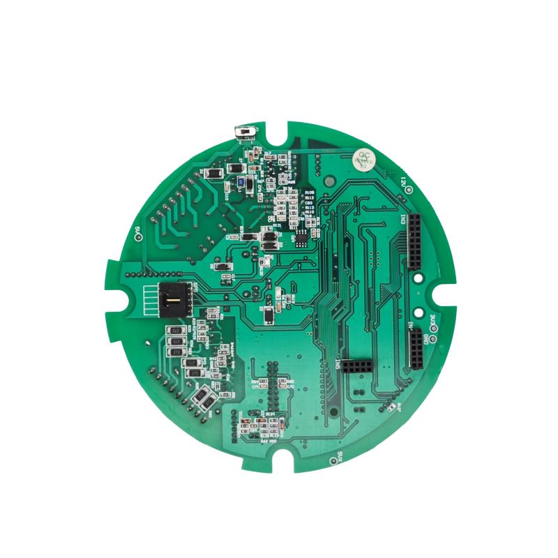
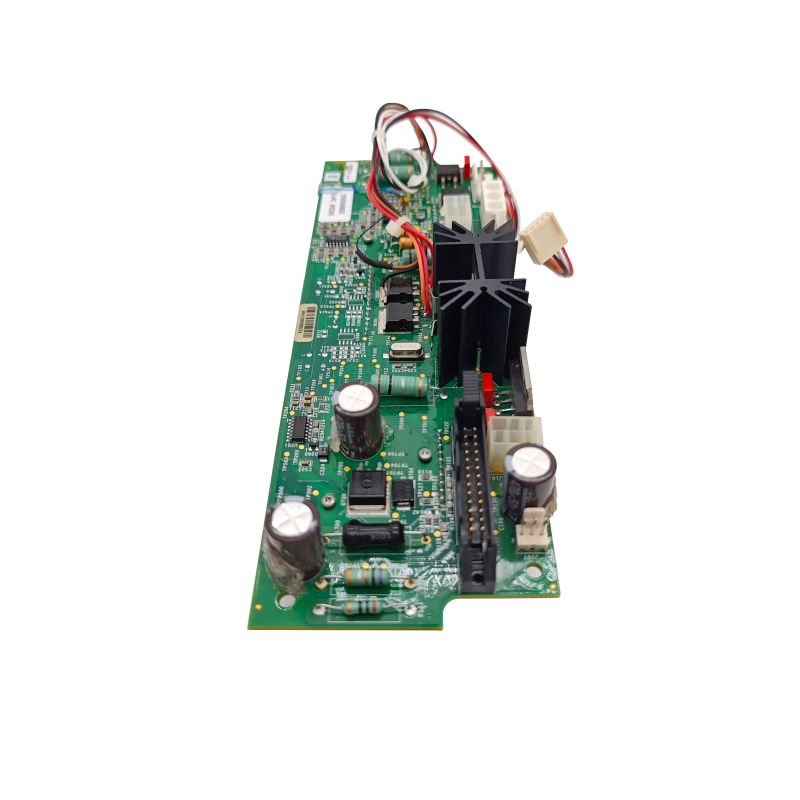
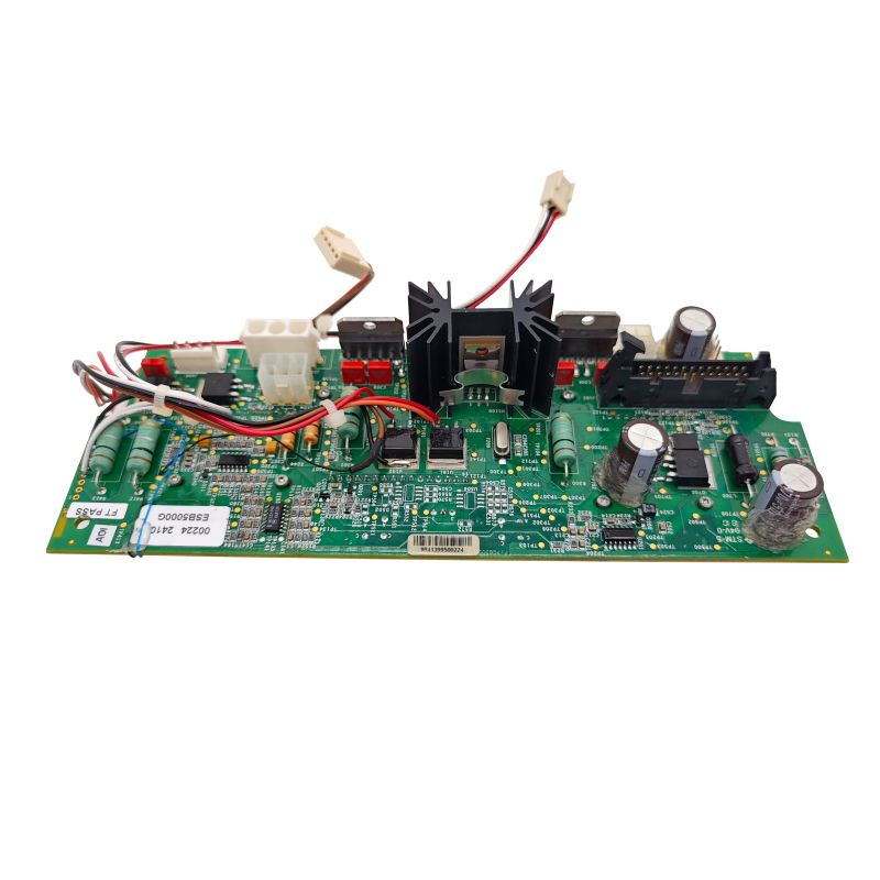
Motor Control PCBA
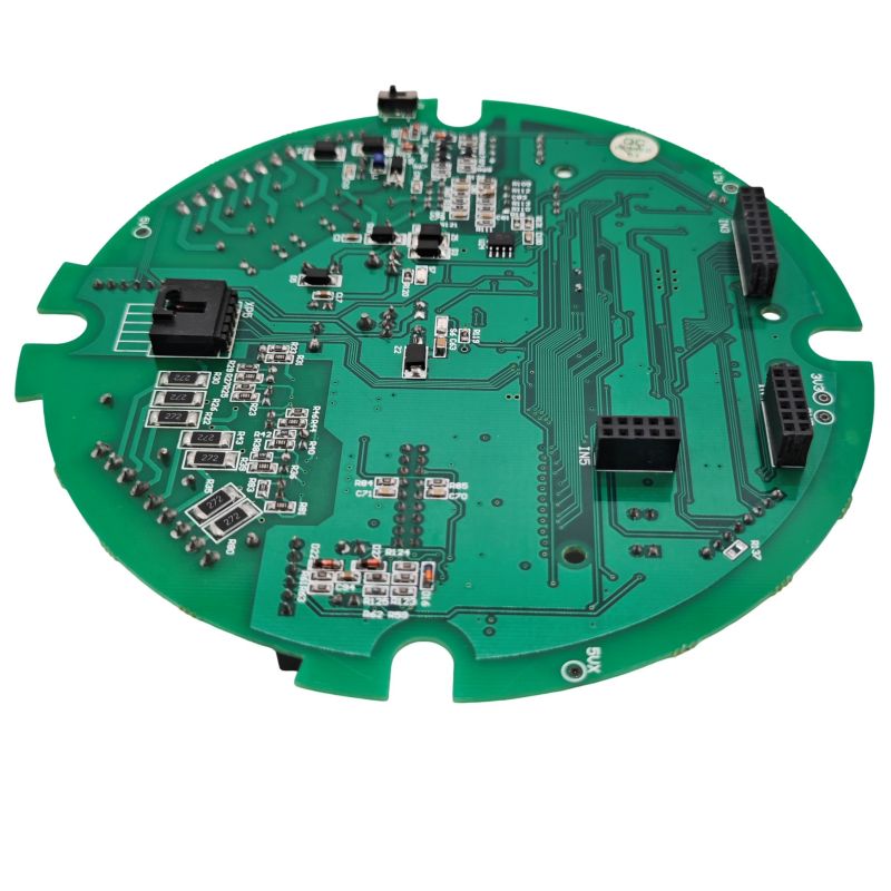
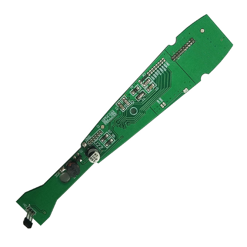
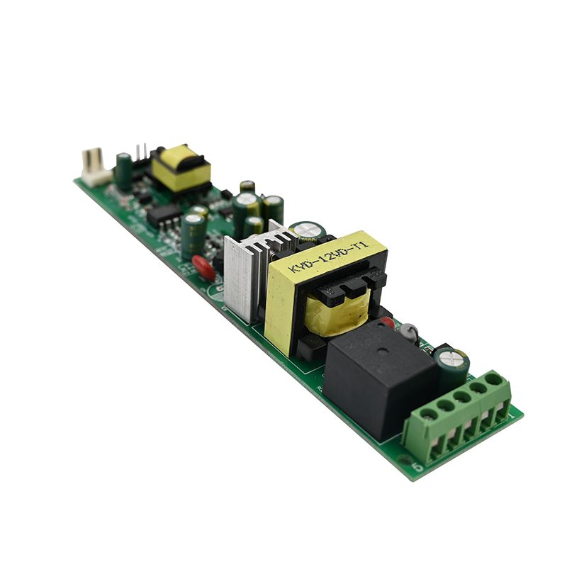
Unixplore Electronics Motor Control PCBA is developed by an experienced China Manufacturer specializing in high-reliability PCB assembly solutions. Designed for industrial drives, EV controllers, servo systems, and automation equipment, this Motor Control PCBA delivers stable performance under vibration, thermal cycling, and long-term operating conditions with customized manufacturing support.
Send Inquiry
Product Description
Table of Contents
- The Short Answer
- Technical Differences
- Why Motor Control PCBAs Face Unique Challenges
- When You MUST Use Lead-Free
- When You Can Justify Leaded Solder (Exemptions)
- Critical Component Considerations
- Best Practices for Lead-Free Motor Control PCBA
- FAQs
- Decision Matrix
The Short Answer: It Depends on Your Application
With 20 years of experience in power electronics and failure analysis across industrial drives, EV controllers, and servo systems, I have documented how soldering decisions make or break motor control reliability. This guide provides engineering data, comparative tables, and field-tested recommendations.
Lead-free soldering is mandatory for most commercial motor control products shipping to regulated markets (EU, China, Korea). However, exemptions exist for automotive under-hood applications, aerospace, and certain industrial drives where reliability overrides regulatory requirements.
| Application Category | Soldering Requirement | Primary Driver |
|---|---|---|
| Consumer motor controls (EU/UK/CN) | Mandatory lead-free | RoHS compliance |
| Consumer motor controls (USA) | Recommended lead-free | Market access & sustainability |
| Automotive under-hood ECUs | Case-by-case exemption possible | Reliability & vibration resistance |
| Industrial drives (10+ year life) | Evaluate both | Long-term fatigue performance |
| Aerospace / Military | Exempt (leaded permitted) | Proven reliability in extreme conditions |
| Repair / Replacement parts | Follow original assembly | Compatibility with existing solder |
Technical Differences: Leaded vs. Lead-Free Solder
Understanding the material properties explains why this decision matters for motor control PCBAs.
Alloy Composition & Melting Points
| Property | Leaded (Sn63/Pb37) | Lead-Free (SAC305) |
|---|---|---|
| Composition | 63% Tin, 37% Lead | 96.5% Tin, 3% Silver, 0.5% Copper |
| Melting Point | 183°C (eutectic) | 217°C to 220°C |
| Reflow Peak Temperature | 220°C to 230°C | 245°C to 260°C |
| Surface Tension | Lower (better wetting) | Higher (poorer wetting) |
| Ductility | Excellent (flexible joints) | Reduced (brittle joints) |
Mechanical Reliability Comparison
| Property | Leaded (Sn63/Pb37) | Lead-Free (SAC305) |
|---|---|---|
| Vibration Resistance | Superior | Reduced (fails 10x faster in some tests) |
| Thermal Fatigue Life | Baseline | Comparable with optimized profile |
| Creep Resistance | Good | Excellent (silver content strengthens joint) |
| Tin Whisker Risk | None (lead suppresses growth) | Present on pure tin finishes |
| Ductility at Low Temp | Maintains flexibility | Becomes brittle below -20°C |
Why Motor Control PCBAs Face Unique Soldering Challenges
Motor control assemblies experience stresses that most PCBs never encounter. These three factors make soldering choice critical.
1. High Vibration Environments
Motor controllers mounted directly on pumps, compressors, or EVs experience continuous mechanical excitation. One documented study compared identical PCBAs with leaded vs. lead-free solder:
- Leaded assembly: First failures after 40 hours of 6g random vibration (component leg fracture)
- Lead-free assembly: Same failure mode after only 4 hours of identical vibration
The cause? Lead-free solder has reduced ductility. When the joint cannot flex, vibration stress concentrates on the component lead, causing premature fracture.
2. Extreme Thermal Cycling
Motor drives generate heat. Then motors stop. Then they start again. A typical industrial drive cycles from -40°C to +125°C thousands of times.
Leaded solder accommodates CTE (coefficient of thermal expansion) mismatches between components and PCB through ductility.
Lead-free solder forms thicker, more brittle intermetallic compounds (IMCs) at the joint interface. Excessive IMC growth weakens the interface and accelerates crack initiation.
3. High Currents and Joule Heating
Motor control PCBAs carry continuous currents from 5A to 200A+. Each solder joint experiences self-heating from I²R losses.
| Current | Leaded Joint Temp Rise | Lead-Free Joint Temp Rise |
|---|---|---|
| 10A (2mm trace) | ~5°C | ~5°C (similar) |
| 30A (with sense resistor) | ~15°C | ~15°C (similar) |
The primary difference is not resistance but how the joint handles thermal cycling stress over time.
When You MUST Use Lead-Free Solder
Regulatory requirements leave little room for choice in these scenarios.
RoHS-Compliant Markets
The EU, China, South Korea, and many other jurisdictions restrict lead in electronics to 0.1% by weight of homogeneous material. Products sold in these markets must use lead-free solder unless a specific exemption applies.
Consumer and Commercial Motor Controls
Household appliances (washing machines, HVAC fans, refrigerator compressors)
Power tools with motor drives
Commercial HVAC controllers
Robotics for non-industrial use
Export-Facing Manufacturing
If you manufacture motor control PCBAs for global distribution, maintaining separate leaded and lead-free production lines creates inventory complexity and quality risks. Unified lead-free processing is the practical choice.
When You Can Justify Leaded Solder (Exemptions)
Certain applications qualify for RoHS exemptions or fall outside regulatory scope entirely.
Automotive Under-Hood Electronics
Exemption 7(c)-I (valid through at least 2026) permits lead in high-reliability automotive electronics where lead-free alternatives lack proven reliability.
Real-world data from Tier-1 suppliers shows:
- Lead-free joints in engine control units show earlier crack initiation under thermal cycling
- Tin whisker formation on pure tin finishes creates short-circuit risks in sealed ECUs
- Many automotive OEMs continue specifying leaded solder for safety-critical modules
Aerospace and Military
Complete exemption. Lead-free solder is not required for aviation, defense, or space applications. These sectors continue using Sn63/Pb37 based on decades of reliability data.
Industrial Motor Drives (10+ Year Life Requirements)
When a motor controller must operate for 15+ years in an unairconditioned factory (-20°C to +70°C ambient), leaded solder remains the conservative choice. The long-term thermal fatigue data for lead-free in these conditions is still developing.
Medical Equipment (Non-Implantable)
Exemptions exist for many medical electronic devices where reliability directly impacts patient safety.
Repair and Replacement Parts
Replacement PCBAs for existing leaded-solder equipment should use leaded solder to maintain metallurgical compatibility with existing joints and components.
Critical Component Considerations for Motor Control PCBA
Not all parts tolerate lead-free soldering temperatures. These five categories require special attention.
1. Temperature-Sensitive Components
Lead-free reflow peaks at 245°C to 260°C—substantially higher than leaded's 220°C to 230°C.
| Component Type | Risk with Lead-Free | Mitigation |
|---|---|---|
| Electrolytic capacitors | Internal electrolyte damage | Verify 260°C rating |
| Plastic-encapsulated ICs | Package cracking (popcorning) | Pre-baking per J-STD-020 |
| Connectors with plastic housings | Warpage or melting | Use high-temp grade connectors |
| Sensors (pressure, temp) | Calibration shift | Verify thermal budget |
| FPGAs / large BGAs | Board warpage | Verify co-planarity after reflow |
2. Components with Pure Tin Finishes
Pure tin finishes (common on lead-free components) can grow conductive whiskers over time—a critical risk for motor controls with tight component spacing.
Mitigation strategies:
- Specify NiPdAu or matte tin-bismuth finishes instead of pure tin
- Apply conformal coating over all solder joints
- Avoid pure tin on components in high-density areas
3. Existing Inventory of Leaded Components
Using leaded-solder components (e.g., SnPb-plated leads) in a lead-free assembly process creates process incompatibility:
The component finish melts at 183°C, but the lead-free solder requires 245°C+
The component finish may oxidize or dissolve before the solder joint forms
Result: unreliable joints, head-in-pillow defects, and field failures
Rule: Use components rated for the soldering process they will experience.
Best Practices for Lead-Free Motor Control PCBA
If lead-free is required, these practices maximize reliability.
PCB Surface Finish Selection
| Finish | Lead-Free Compatibility | Cost | Best For |
|---|---|---|---|
| ENIG | Excellent | High | Mission-critical modules (ADAS, safety) |
| Immersion Silver | Good | Medium | General motor control |
| OSP | Good | Low | High-volume, short-shelf-life |
| HASL (leaded) | Not compatible | Low | Avoid entirely for lead-free |
| HASL (lead-free) | Acceptable | Medium | Cost-sensitive, non-critical |
Recommendation: ENIG provides the best wetting and longest shelf life for lead-free assembly.
Reflow Profile Optimization
A poorly optimized lead-free reflow profile creates cold joints, voids, and brittle IMCs.
| Parameter | Target Setting |
|---|---|
| Ramp rate (preheat) | 1°C to 2°C per second (avoid thermal shock) |
| Soak temperature | 150°C to 180°C for 60-90 seconds |
| Time above liquidus (TAL) | 60 to 90 seconds |
| Peak temperature | 245°C to 260°C (component-dependent) |
| Cooling rate | Controlled 2°C to 4°C per second (not rapid quench) |
Vibration Mitigation for Lead-Free Joints
Given lead-free's reduced ductility in vibration, take these additional steps:
1. Potting / Encapsulation: Fill the enclosure around high-mass components (connectors, transformers, large capacitors) with silicone or urethane potting compound. This transfers vibration stress away from solder joints.
2. Adhesive-bonded components: Use epoxy or silicone adhesive under large surface-mount devices (inductors, aluminum capacitors).
3. Reduce component standoff height: Tall components with long leads act as vibration levers. Specify low-profile components where possible.
Motor Control PCBA FAQs
Below are three technical questions from motor drive designers and manufacturing engineers.
Q1: I am designing an electric vehicle motor controller for a Tier-1 automotive supplier. Can I use lead-free solder?
A: Yes, but with significant qualification testing. Most Tier-1 automotive suppliers currently use lead-free solder for new designs because RoHS compliance is required for EU-market vehicles. However, exemptions exist for under-hood electronics where lead-free reliability data remains incomplete.
Your qualification plan must include:
| Test | Standard | Pass Criteria |
|---|---|---|
| Thermal cycling | -40°C to +125°C, 2000 cycles | No joint cracks (IPC-9701) |
| Vibration | 6g random, 24 hours minimum | No electrical intermittency |
| Tin whisker | 85°C/85% RH, 3000 hours | No whiskers >50µm |
| High-temperature storage | 150°C, 1000 hours | No IMC overgrowth >5µm |
Practical advice: Many automotive OEMs continue specifying leaded solder for under-hood ECUs using the existing RoHS exemption. Discuss with your customer before committing to lead-free. If lead-free is mandatory, specify ENIG surface finish and conformal coating for all assemblies.
Q2: My industrial motor drive failed after 18 months with cracked solder joints on the six power MOSFETs. The assembly uses SAC305 lead-free solder. What went wrong?
A: This is a classic thermal fatigue failure. Here is the diagnostic sequence:
Step 1 - Examine the crack locations: Under a microscope, look at the interface between the MOSFET lead and the solder fillet. If the crack runs along the intermetallic compound (IMC) layer, the IMC grew too thick during reflow.
Step 2 - Review your reflow profile: For SAC305, the time above liquidus (TAL) should be 60 to 90 seconds maximum. If your TAL exceeded 120 seconds, IMC thickness can exceed 10µm (the brittle zone begins above 5µm).
Step 3 - Measure temperature rise at the MOSFET drain pad: With an infrared camera, measure the pad temperature at full load. If it exceeds 110°C, the thermal cycling delta (ΔT) is too large.
Step 4 - Check for single-point mounting: Power MOSFETs with large thermal pads (DPAK, D2PAK, TO-263) that lack thermal vias or have voids under the pad experience hot spots. X-ray the joints—voids over 25% of pad area are unacceptable.
Recommended fixes (in order of priority):
1. Reduce ΔT: Add a heatsink or improve airflow to keep MOSFET pads below 90°C at full load.
2. Add thermal vias: Under each MOSFET pad, place an array of 0.3mm vias (filled and capped) to draw heat into the PCB ground plane.
3. Use a low-silver alloy: Consider SAC105 (1% Ag) instead of SAC305. Lower silver content increases ductility and thermal fatigue resistance at the cost of slightly higher melting point.
4. Pot the MOSFETs: Apply thermally conductive potting compound over the MOSFETs. This dampens thermal cycling stress and transfers heat.
Q3: I need to repair a motor control PCBA that originally used leaded solder. Can I use lead-free solder for the repair?
A: Technically yes, but not recommended. Here is why:
Problem 1 - Mixed metallurgy: Lead-free solder (SAC305) does not mix well with residual leaded solder (Sn63/Pb37). The resulting alloy has an unpredictable melting point (typically 190°C to 210°C) and forms weak, grainy joints prone to cracking.
Problem 2 - Temperature conflict: To properly flow lead-free solder, you need a 370°C to 400°C soldering iron tip. This temperature can:
Delaminate the PCB pad from the FR4 substrate
Damage adjacent components (especially electrolytic capacitors)
Melt nearby plastic connectors
Recommended repair protocol:
| Scenario | Best Practice |
|---|---|
| Repairing leaded assembly | Use leaded solder (Sn63/Pb37) for the repair. The small quantity is exempt from RoHS for repair purposes. |
| Replacing a single component | Remove all old solder completely (using solder wick or vacuum desoldering), then re-solder with original alloy type. |
| No access to leaded solder | Desolder completely, clean the pad thoroughly, apply lead-free flux, then use lead-free solder. Iron tip at 370°C maximum. |
| Large-scale rework | Reject the board. Mixing alloys creates unreliable field performance. |
If you must use lead-free on a leaded board: Remove 100% of the existing solder from the repair area using a vacuum desoldering station. Inspect under magnification—any residual leaded solder will contaminate the new joint. Then proceed with lead-free soldering at 370°C with active flux.
Decision Matrix: Leaded vs. Lead-Free for Motor Control PCBA
Use this table to guide your soldering choice.
| If your answer is YES to any row... | ...then choose this solder |
|---|---|
| Product sells to EU, China, Korea, or similar RoHS markets | Lead-Free |
| Product is consumer or commercial grade | Lead-Free |
| Product is automotive under-hood with <5 year expected life | Lead-Free with qualification |
| Product requires 10+ year life in high-vibration environment | Leaded (if exemption applies) |
| Product operates in -40°C to +125°C with daily thermal cycles | Leaded (exemption route) |
| Product is aerospace, military, or medical safety-critical | Leaded (exemption applies) |
| You are repairing an existing leaded-solder assembly | Leaded (use original alloy) |
| You have existing inventory of leaded-solder components | Leaded (process compatibility) |
Lead-free soldering is legally required for most motor control PCBAs shipped to regulated markets. However, the material properties of lead-free alloys—higher brittleness, thicker IMC formation, tin whisker risk—create real reliability concerns in high-vibration and thermal-cycling applications.
For mandatory lead-free applications:
Use ENIG surface finish for best wetting
Control reflow profile carefully (TAL 60-90 seconds, peak 245-260°C)
Add potting or adhesive for high-mass components
Apply conformal coating to mitigate tin whiskers
For applications qualifying for exemptions (automotive under-hood, industrial 10+ year, aerospace, medical):
- Leaded solder (Sn63/Pb37) remains the reliability gold standard
- The combination of ductility, vibration resistance, and decades of field data is difficult to replace
For repairs: Match the original solder alloy. Mixed metallurgy creates unpredictable, unreliable joints.
The decision ultimately balances regulatory compliance against field reliability. For consumer products with 3-5 year expected life, lead-free is mature and reliable. For safety-critical or long-life motor controls, pursue the exemption and use leaded solder.
Hot Tags: Motor Control PCBA, China, Manufacturers, Suppliers, Factory, Customized, Cheap, Quality, Advanced, CE, 1 Year Warranty, Price
Related Category
Home Appliance PCBA
Industrial Control PCBA
Automobile PCBA
Consumer Electronics PCBA
Medical Equipment PCBA
Security System PCBA
Healthcare PCBA
LED Lighting PCBA
IoT PCBA
Electric Gardening Tool PCBA
Send Inquiry
Please Feel free to give your inquiry in the form below. We will reply you in 24 hours.