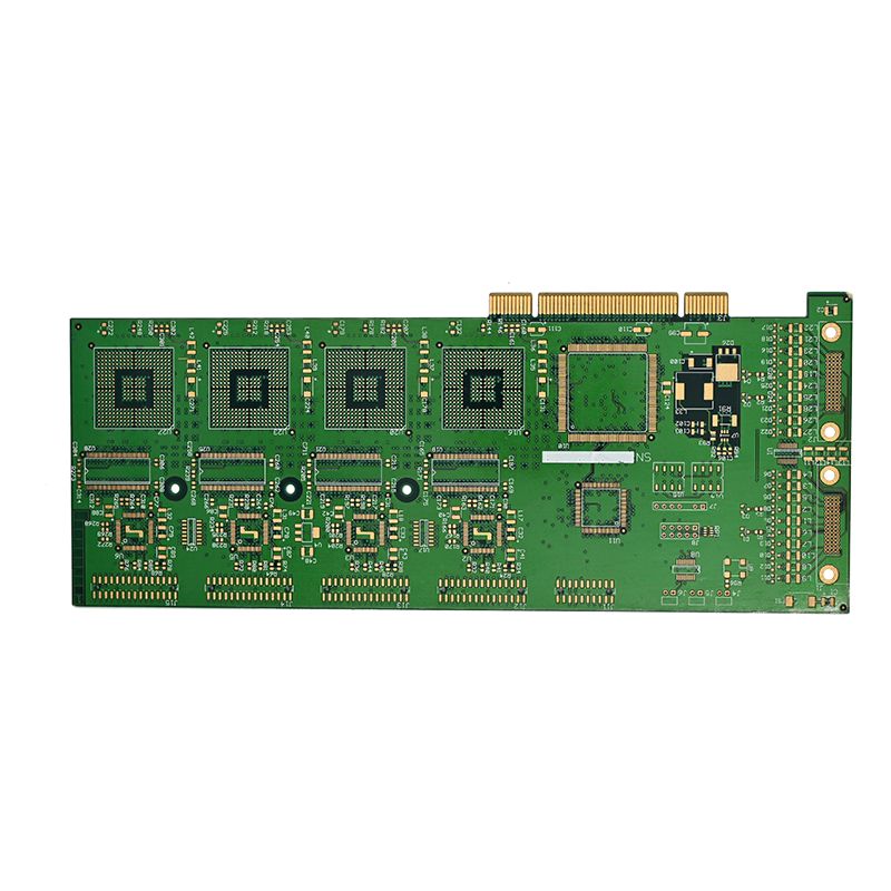
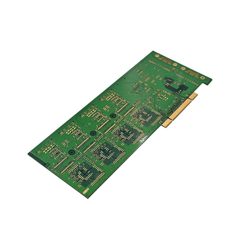
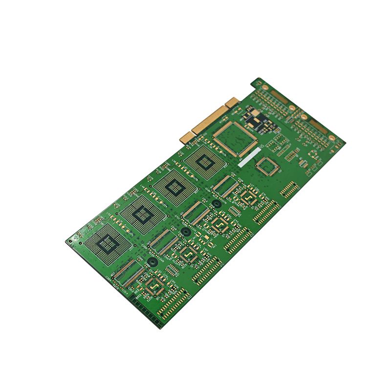
From 1080p to 8K — Unixplore Electronics (est. 2011) provides one-stop turnkey PCBA manufacturing for game console OEMs. With 6 SMT lines, 20 R&D engineers, and a 3,000m² factory, we handle everything from material selection to finished product assembly. Use this guide to make an informed decision — then let us deliver the boards.
Why PCB Type Matters for Game Consoles
A game consoles PCBA handles high-speed interfaces (PCIe, HDMI 2.1, USB 3.2, DDR memory) and power-hungry components (CPU, GPU, voltage regulators). The PCB substrate, copper weight, and layer stack determine:
- Signal integrity at 10+ Gbps (HDMI 2.1 requires 12 Gbps per lane)
- Thermal dissipation from the APU (up to 150W in modern consoles)
- Power delivery impedance (stable 0.8V core voltage)
- Mechanical durability against repeated connector insertion (HDMI, USB)
PCB Material Types — Comparison Table
| Material | Dk | Df | Tg (°C) | Cost | Best For |
|---|---|---|---|---|---|
| FR-4 standard | 4.2-4.6 | 0.020 | 135 | $ | Budget consoles, legacy designs |
| FR-4 high-Tg | 4.2-4.5 | 0.018 | 170 | $$ | Standard 8th/9th gen consoles |
| Mid-loss (e.g., IT-170G) | 3.9-4.1 | 0.012 | 180 | $$$ | HDMI 2.0, DDR4-3200 |
| Low-loss (e.g., Megtron 6) | 3.6-3.8 | 0.006 | 200 | $$$$ | HDMI 2.1, DDR5, PCIe 4.0/5.0 |
| Polyimide | 3.5-3.8 | 0.008 | 260+ | $$$$$ | Flex-rigid, handheld consoles |
Rule of thumb: FR-4 high-Tg is the minimum acceptable for any modern game consoles PCBA targeting 60+ FPS gaming.
Unixplore recommendation: For 4K/60FPS projects, we recommend Mid-loss materials (IT-170G). We stock these materials in-house for faster lead times.
Layer Count — How Many Layers Does Your Console Need?
| Layer count | Typical use case | Cost multiplier |
|---|---|---|
| 4 layers | Retro console clone, low-end handheld | 1.0x (baseline) |
| 6 layers | Entry-level console (1080p, 30 FPS) | 1.4x |
| 8 layers | Mid-range (4K, 60 FPS, basic HDR) | 1.8x |
| 10 layers | High-end (4K/120 FPS, HDMI 2.1, VRR) | 2.3x |
| 12+ layers | Premium (8K support, advanced cooling) | 3.0x+ |
Layer stack recommendation for an 8-layer game consoles PCBA:
- Layer 1 — Top signal (critical traces: HDMI, DDR, PCIe)
- Layer 2 — Ground (continuous reference plane)
- Layer 3 — Signal (slower I/O: USB, audio, buttons)
- Layer 4 — Power (core VDD, VDDCR, split planes)
- Layer 5 — Power (IO voltage, DRAM VDDQ)
- Layer 6 — Signal (secondary high-speed)
- Layer 7 — Ground (return path for bottom signals)
- Layer 8 — Bottom signal (general routing, components)
Unixplore recommendation: We have manufactured 8-layer boards for custom consoles with SoCs similar to AMD Van Gogh. For high-end designs (Rembrandt / Meteor Lake class), our 10-layer capability with blind/buried vias ensures signal integrity. Send us your BGA ballmap — we will validate the layer count within 24 hours.
Critical Parameters for Game Consoles PCBA
Impedance Control
High-speed interfaces require controlled impedance. Typical targets for a game consoles PCBA:
| Interface | Differential impedance | Tolerance |
|---|---|---|
| HDMI 2.1 (4 lanes) | 100Ω ±10% | 5% recommended |
| USB 3.2 Gen 2 | 90Ω ±10% | 10% acceptable |
| PCIe 4.0 / 5.0 | 85Ω ±10% | 5% recommended |
| DDR4 / DDR5 | 40Ω (single), 80Ω (diff clock) | 8% |
Achieving these requires precise trace width/spacing and dielectric thickness — use a stackup calculator (e.g., Polar Si9000) before layout.
Copper Weight and Current Capacity
| Component / Rail | Required copper | Trace width (for 1A, 1oz) |
|---|---|---|
| CPU/GPU core (50A+) | 2 oz (outer), 1.5 oz (inner) | Power planes, not traces |
| DDR memory VDDQ (5A) | 1 oz | 2mm minimum |
| USB 5V (0.9A) | 1 oz | 0.6mm |
| HDMI 5V (0.05A) | 0.5 oz | 0.25mm |
Critical note: For high-current rails (>10A), use 2oz copper on outer layers and add thermal vias directly under the voltage regulator module (VRM). Unixplore supports 2oz copper standard on power layers.
Via Technology
| Via type | Cost | Signal quality | Application |
|---|---|---|---|
| Through-hole | Low | Good (but stubs cause reflections) | Power, slow I/O |
| Blind via | Medium | Better | DDR routing from SoC to memory |
| Buried via | High | Best | Dense BGA fanout |
| Via-in-pad (filled) | High | Best (no stub) | High-speed > 5 Gbps |
For HDMI 2.1 or PCIe 4.0, use via-in-pad for BGA escape. Avoid standard through-hole vias on these signals — the stub will cause insertion loss exceeding 3dB at 10 GHz.
Surface Finish Options for Game Consoles PCBA
| Finish | Durability | Solderability | Cost | Console tier |
|---|---|---|---|---|
| HASL | Poor (uneven) | Good | $ | Retro only |
| ENIG | Excellent (flat) | Excellent | $$$ | All modern consoles |
| Immersion Silver | Good | Good | $$ | Budget handhelds |
| OSP | Fair (short shelf life) | Very good | $ | Short-run prototypes |
Recommendation: ENIG is mandatory for any game consoles PCBA with BGA components (SoC, GPU, DDR chips). HASL creates uneven pads causing BGA head-in-pillow defects. OSP oxidizes within 6 months — unsuitable for mass production.
Unixplore standard: We use ENIG as our default finish for all BGA-based console PCBA projects. Our ENIG line supports panel sizes up to 600×500mm, and we maintain IPC-610E Class 2/3 standards.
Thermal Management — PCB as a Heatsink
Modern game console SoCs generate 80–150W. The game consoles PCBA must help dissipate heat.
Thermal design checklist:
- Thermal vias under the SoC: 0.3mm diameter, 1.0mm pitch, at least 100 vias
- Copper pour on layer 2 (ground) directly under the SoC — no breaks
- Thermal relief spokes — remove them on high-current pads (use full contact)
- Metal-core PCB (optional) — aluminum substrate for extreme cooling, but increases cost 3x and limits layer count to 2–4 layers
For a standard 8-layer FR-4 high-Tg board with 2oz copper, the PCB alone dissipates about 5–8W. The rest requires a separate heatsink and fan.
High-Signal Integrity Layout Rules
| Rule category | Requirement for game consoles PCBA |
|---|---|
| HDMI differential pair length match | ±5 mils (0.127mm) within each pair |
| HDMI pair-to-pair length match | ±50 mils (1.27mm) |
| USB 3.2 differential pair | 90Ω, length match ±2 mils |
| DDR clock to DQS skew | ≤ 15ps (approx. 2.5mm trace length) |
| Maximum stub length on high-speed signals | ≤ 15 mils (use back-drilled vias) |
Avoid 90-degree corners on any signal above 1 Gbps — use 45-degree chamfers or arcs.
Game Consoles PCBA — Frequently Asked Questions
FAQ 1 — Can I use standard FR-4 for a PlayStation or Xbox level console PCBA?
Answer: No, standard FR-4 (Tg 135°C, Df 0.020) is insufficient for a modern game consoles PCBA targeting 4K/60FPS or higher. Here is why:
- Thermal: SoC junction temperature reaches 90–95°C during gaming. The PCB near the BGA can exceed 125°C with standard FR-4, exceeding its glass transition temperature (Tg) and causing board warpage. Warpage cracks BGA solder joints after 500–1,000 thermal cycles.
- Signal loss: At 6 GHz (HDMI 2.1 fundamental frequency), standard FR-4 has insertion loss of approximately 1.0 dB per inch. A typical 6-inch HDMI trace loses 6 dB — half the signal power. Eye diagram closes, causing intermittent black screens or HDCP handshake failures.
- Dielectric absorption: Standard FR-4 absorbs moisture, changing dielectric constant (Dk) over time. For DDR memory, Dk drift shifts impedance by ±15%, causing bit errors and system crashes.
Minimum acceptable material: FR-4 high-Tg (≥170°C) with Df ≤ 0.018. For any console with HDMI 2.1 or PCIe 4.0, upgrade to mid-loss (e.g., IT-170G) or low-loss (Megtron 6) materials. The added $8–$15 per board is essential for reliability.
FAQ 2 — How do I choose between 8-layer and 10-layer for a game consoles PCBA?
Answer: The decision between 8-layer and 10-layer for a game consoles PCBA depends on your BGA density and memory topology. Use this selection matrix:
| Requirement | 8-layer sufficient? | 10-layer required? |
|---|---|---|
| SoC BGA pitch ≥ 0.8mm, pin count < 600 | Yes | No |
| SoC BGA pitch 0.65mm, pin count 600-800 | Marginal (complex routing) | Yes |
| SoC BGA pitch ≤ 0.5mm, pin count > 800 | No — impossible to fan out | Yes |
| Two DDR4/5 channels (4 chips total) | Yes | No |
| Four DDR channels (8 chips total) | No — not enough routing channels | Yes |
| PCIe 4.0 x8 or more | No (crosstalk difficult to control) | Yes |
| Budget constraint (<$8 per board) | Yes | No (10-layer costs 30% more) |
Cost-benefit rule: Design 8-layer first. If your autorouter fails to achieve 85% completion or you violate spacing rules on more than 10 nets, move to 10-layer. In our experience, most custom consoles with mid-range SoCs (similar to AMD Van Gogh) work well on 8-layer. High-end designs (similar to AMD Rembrandt or Intel Meteor Lake) require 10-layer for signal integrity.
FAQ 3 — What is the minimum trace width and spacing for HDMI 2.1 on a game consoles PCBA?
Answer: For a game consoles PCBA with HDMI 2.1 (12 Gbps per lane, 4 lanes), trace geometry is determined by your PCB material and layer stack. Here are proven values for common materials:
On mid-loss material (Dk = 4.0, 8-layer stack, 5 mil prepreg):
- Trace width: 4.5 mils (0.114mm)
- Spacing (intra-pair): 4.5 mils (edge-to-edge)
- Spacing to adjacent pairs or signals: ≥ 12 mils (0.305mm)
On low-loss material (Dk = 3.7, same stack):
- Trace width: 5.0 mils (0.127mm)
- Spacing (intra-pair): 5.0 mils
- Spacing to other signals: ≥ 10 mils
Critical requirements beyond trace width:
- Length match: ±5 mils (0.127mm) between D+ and D- inside each pair
- Skew between pairs: ≤ 50 mils (1.27mm) — this is tighter than HDMI spec but required for 12 Gbps
- Via count: Maximum 2 vias per HDMI signal (one from SoC to inner layer, one from inner layer to HDMI connector)
- AC coupling capacitors: 0.1µF, 0402 size, placed within 100 mils of the HDMI connector, not near the SoC
- Reference plane: Entire HDMI route must reference solid ground (no splits or voids)
Violate any of these, and HDMI compliance test (CTS 2.1) will fail. Common symptoms: intermittent 4K/120Hz, blank screen on HDCP handshake, or snow on VRR content.
PCB Selection Quick Decision Flowchart
Start: What is your target resolution/frame rate?
│
├── 1080p / 30 FPS or retro console
│   └── FR-4 high-Tg, 6-layer, ENIG, 1oz copper → acceptable
│
├── 4K / 60 FPS, HDMI 2.0, DDR4
│   └── Mid-loss material, 8-layer, ENIG, 1oz/2oz mix → recommended
│
└── 4K / 120 FPS or 8K, HDMI 2.1, DDR5, PCIe 4.0/5.0
    └── Low-loss material, 10-layer minimum, ENIG, 2oz power layers → mandatory
Final Checklist — Before Ordering Your Game Consoles PCBA
- Material selected based on signal speed (FR-4 HT / mid-loss / low-loss)
- Layer count validated against BGA pinout and memory channels
- Impedance control requirements documented for each high-speed interface
- Thermal vias placed under SoC and VRM components
- Surface finish = ENIG for BGA reliability
- Manufacturing DFM review — minimum annular ring, solder mask slivers
- Test points accessible for in-circuit test (ICT)
For a stackup recommendation tailored to your specific SoC and memory configuration, send your BGA ballmap and target console specifications (resolution, FPS, memory type).
Why Unixplore — Your PCBA Manufacturing Partner Since 2011
Production Capacity
- 1.5M+ PCBAs per year
- 150,000 finished product assemblies per year
- 3,000m² self-owned factory
- 6 SMT lines + 4 DIP lines + 2 assembly lines
Engineering & Quality
- 20 R&D engineers
- ISO 9001:2015 & IPC-610E
- 2 Aging test rooms + 2 High/Low temperature test rooms
- In-house functional & reliability testing
Global Reach
- 35% Western Europe | 20% North America | 20% Oceania | 10% South America
- Sales support in English, French, Russian, Arabic
One-Stop Turnkey Services
- PCB/PCBA design & fabrication
- Parts procurement & SMT/DIP assembly
- Conformal coating & box building
- Wire harness & finished product assembly
Applications: Home Appliance · Automotive · Security · Consumer Electronics · Industrial Control · Medical · Healthcare · Smart Home · Military · Aviation
Contact us today for any customized electronic assemblies project. No MOQ. Small quantity welcome.