- English
- Español
- Português
- русский
- Français
- 日本語
- Deutsch
- tiếng Việt
- Italiano
- Nederlands
- ภาษาไทย
- Polski
- 한국어
- Svenska
- magyar
- Malay
- বাংলা ভাষার
- Dansk
- Suomi
- हिन्दी
- Pilipino
- Türkçe
- Gaeilge
- العربية
- Indonesia
- Norsk
- تمل
- český
- ελληνικά
- український
- Javanese
- فارسی
- தமிழ்
- తెలుగు
- नेपाली
- Burmese
- български
- ລາວ
- Latine
- Қазақша
- Euskal
- Azərbaycan
- Slovenský jazyk
- Македонски
- Lietuvos
- Eesti Keel
- Română
- Slovenski
- मराठी
- Srpski језик

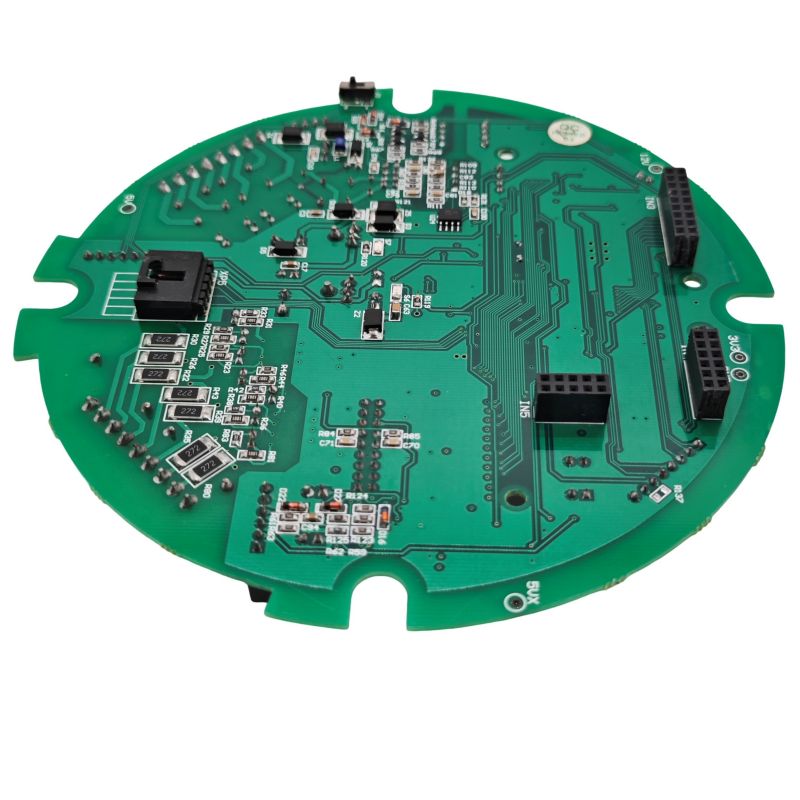
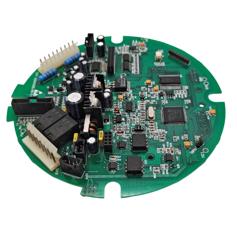
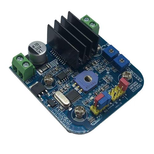
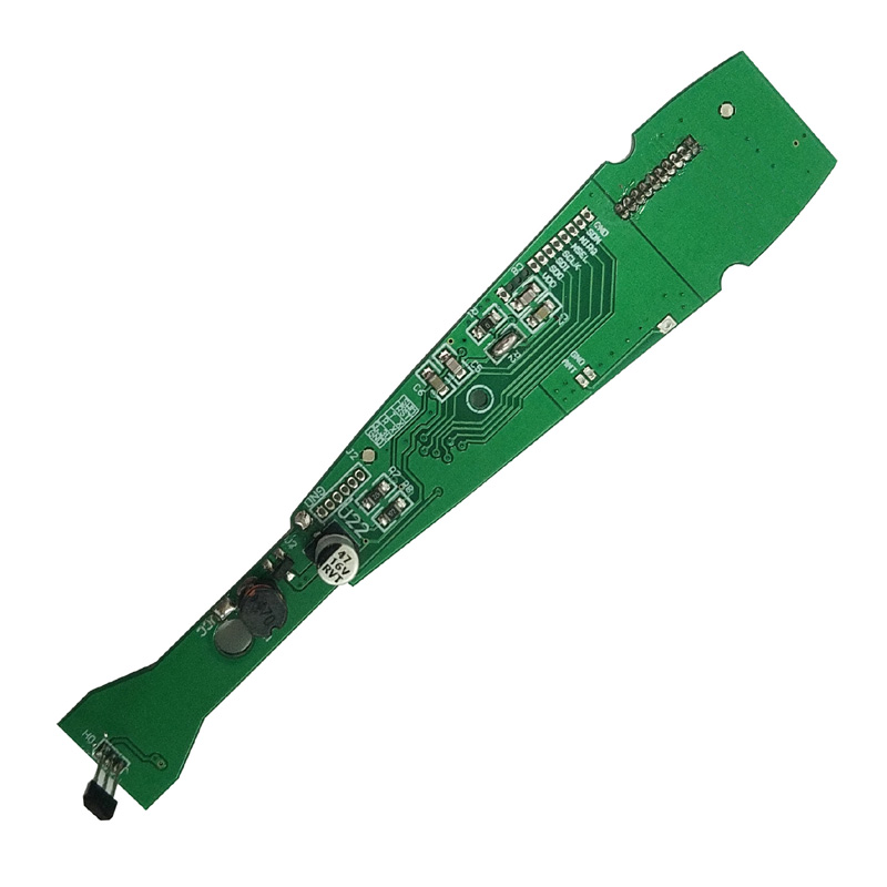
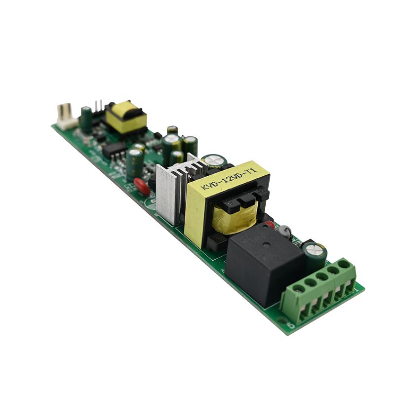
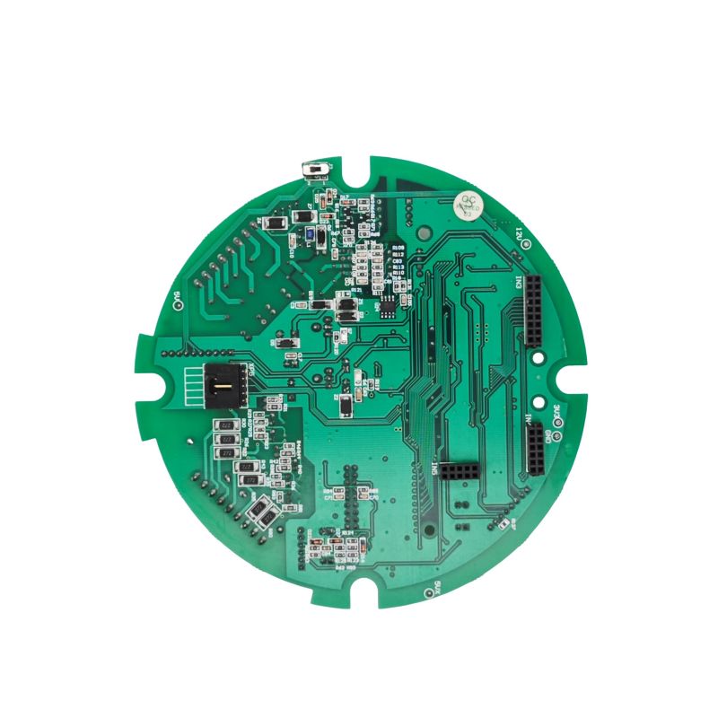
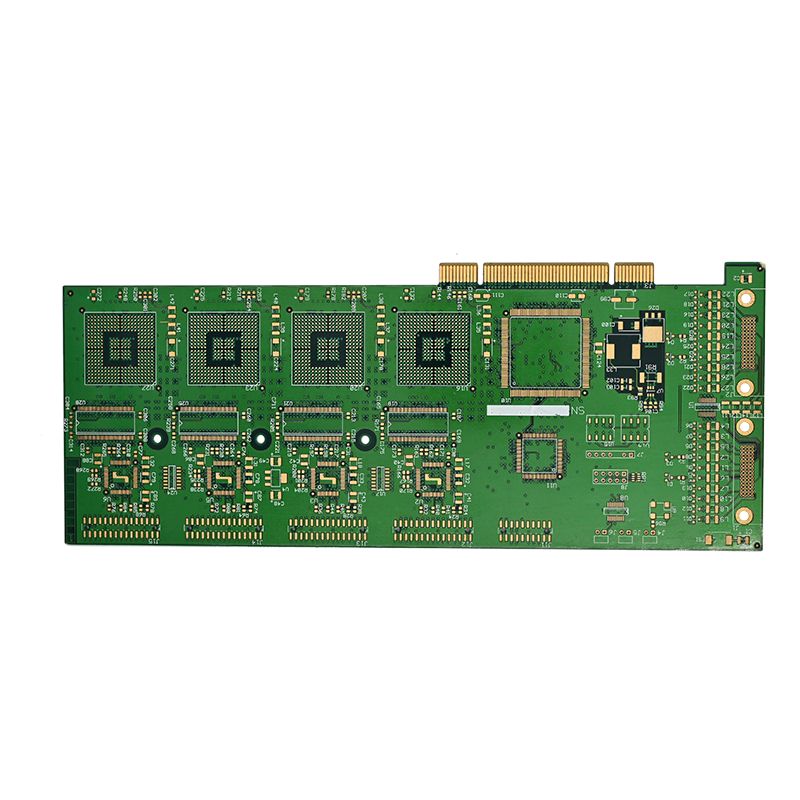
RC servo PCBA
Unixplore Electronics delivers engineering-grade RC servo PCBA solutions — from standalone driver boards to multi-channel servo controllers and internal servo replacement boards. Contact us today to discuss your servo PCBA project — and get it right the first time.
Send Inquiry
Product Description
Unixplore Electronics — With 20 years of embedded systems and PCB design experience, we have seen the same failure patterns repeatedly: noisy power lines, inadequate decoupling, and incorrect PWM routing. Our servo PCBA solutions are built around the engineering specifications, layout rules, and testing methods that professional designers actually use in production.
Whether you need a standalone driver board, a multi-channel servo controller, or an internal servo control board replacement, Unixplore Electronics delivers reliable, noise-immune PCBA that performs in both RC hobby and industrial robotics environments.
What we offer:
- Full servo PCBA design (schematic + layout) in Altium, KiCad, or your preferred format
- Prototyping with functional testing (load, ripple, thermal reports)
- Volume manufacturing with component sourcing and SMT assembly
- Design review and failure analysis consulting
What an RC Servo PCBA Must Do
An RC servo PCBA (whether a standalone driver board or the internal servo control board) performs three essential functions:
- PWM Signal Generation or Reception: Converts control pulses (1ms to 2ms at 50Hz) into position commands.
- Power Distribution: Delivers clean 5V or 6V to the servo motor and control IC.
- Feedback Processing: Reads the internal potentiometer to verify position and close the control loop.
High-reliability designs also include current sensing for overload detection and opto-isolation for noise immunity.
Core Technical Specifications
The following parameters represent industry standards for RC servo control PCBA designs. These apply to both dedicated servo driver boards and integrated receiver PCBA assemblies.
Input Power Specifications
| Parameter | Standard RC (Hobby) | High-Performance (Industrial) |
|---|---|---|
| Input Voltage | 4.8V to 6.0V (4–5 NiMH cells) | 6.0V to 8.4V (2S LiPo direct) |
| Max Continuous Current (per servo) | 500mA to 1.5A | 2A to 5A |
| Peak Stall Current | 1.5A to 3A | 5A to 10A |
| Voltage Ripple Tolerance | < 5% (240mV on 4.8V supply) | < 3% (180mV on 6V supply) |
Control Signal Specifications
| Parameter | Value | Notes |
|---|---|---|
| PWM Frequency | 50Hz (20ms period) | Industry standard |
| Pulse Width Range | 1000µs to 2000µs | 1500µs = center position |
| Pulse Width Resolution | 1µs to 5µs | 8-bit to 10-bit effective resolution |
| Logic High Level | 3.3V or 5V (3.3V tolerant) | Check MCU compatibility |
| Minimum Pulse Detection | 500µs to 700µs | For fail-safe detection |
Internal Servo PCBA Components (Inside the Servo)
A standard RC servo contains a small PCBA with these components:
| Component | Function | Typical Specification |
|---|---|---|
| Control IC | Decodes PWM, drives H-bridge | Custom or general-purpose MCU |
| H-Bridge MOSFETs | Drives motor forward/reverse | 2A to 5A rating |
| Potentiometer | Position feedback | 5kΩ to 10kΩ linear taper |
| Voltage Regulator | Powers control IC | 5V or 3.3V LDO |
| Decoupling Capacitors | Noise filtering | 100µF electrolytic + 100nF ceramic |
PCBA Layout Rules for RC Servo Reliability
At Unixplore Electronics, we know that most RC servo failures originate on the PCB. We follow these 8 rules to ensure reliable operation in every design we deliver.
1. Power Distribution: Star Grounding
- Never daisy-chain ground. Each servo ground should return directly to the power supply ground point.
- Separate power and signal ground. On multi-servo PCBA designs, split the ground plane and connect at a single point near the battery input.
- Trace width for power: For 1.5A continuous current, use 1.5mm minimum trace width with 1oz copper.
2. Decoupling Capacitor Placement
Servo motors generate significant electrical noise. A typical servo can produce up to 200mV peak-to-peak noise on the 5V supply line.
Required decoupling per servo connector:
- 100µF to 470µF electrolytic capacitor (handles motor inrush)
- 100nF ceramic capacitor (filters high-frequency noise)
- Place capacitors within 10mm of the servo power pins
Bulk capacitance for the entire PCBA: Add a large capacitor (1000µF to 4700µF) at the main power input. This prevents brownouts when multiple servos start simultaneously.
3. PWM Signal Routing
- Keep PWM traces short and direct. Long traces act as antennas for noise.
- Avoid running PWM traces parallel to power wires. Use 90-degree crossing if necessary.
- Add a 100Ω to 470Ω series resistor on the PWM output pin. This limits current during fault conditions and reduces ringing.
4. Servo Connector Layout
The standard 3-pin servo connector (signal, VCC, ground) requires specific spacing:
- Pin spacing: 2.54mm (0.1 inch) or 2.7mm (high-density)
- PCB thickness for connector block: 1.2mm to 1.6mm
- Signal pin location: Typically the inner pin (pin 2 of 3)
- Power sequencing: GND must connect before VCC on insertion
For high-density designs, 2.7mm spacing between servo connectors allows compact layout while maintaining reliable connections.
5. Voltage Regulation for the Control MCU
- Use a separate LDO for the MCU if the same supply powers servos. Servo current spikes cause voltage dips that can reset the microcontroller.
- Recommended regulator: 5V or 3.3V LDO with at least 200mA capacity and 1µF input/output capacitors.
- Protection diode: Add a 1N4007 or Schottky diode on the input to protect against reverse polarity.
6. Noise Suppression on the Motor (For Internal Servo PCBA Design)
If designing a PCBA that goes inside a servo, add noise suppression directly at the motor terminals:
- 100nF ceramic capacitor soldered directly across the motor terminals.
- Connect capacitor negative to motor housing for additional shielding (reduces noise by up to 200mV).
- Optional: Add ferrite beads on motor leads for extreme noise environments.
7. Current Sensing for Overload Detection
Advanced servo PCBA designs include current monitoring:
- Shunt resistor: 0.1Ω to 0.5Ω, 1% tolerance — creates voltage proportional to current
- Differential amplifier: Gain of 10 to 20 — amplifies shunt voltage to measurable level
- ADC input: 10-bit minimum — feeds current data to control MCU
A 100mΩ shunt produces 50mV at 500mA and 150mV at 1.5A. With a 5x gain amplifier, this becomes 250mV to 750mV, suitable for 3.3V ADC inputs.
8. Insulation and Mechanical Protection
Internal servo PCBA boards must be physically protected:
- Insulating tape: Place electrical tape between the PCBA and the metal servo case. This prevents short circuits from solder joints or component leads touching the case.
- Conformal coating: For outdoor or high-humidity applications, add acrylic conformal coating to prevent corrosion.
Control Signal Generation (MCU Code Considerations)
Proper PWM generation is critical for jitter-free operation. Here are the key parameters:
PWM Configuration
| Parameter | Setting |
|---|---|
| PWM frequency | 50Hz (period = 20ms) |
| Pulse width range | 1000µs to 2000µs (center = 1500µs) |
| Timer resolution | At least 8-bit (1µs steps require 16-bit timer) |
| Update rate | 50Hz minimum (every 20ms) |
MCU Code Example Pseudocode
    // Calculate duty cycle for 1500µs pulse
    // Assumes PWM period = 20ms, clock = 1MHz prescaler

    pulse_width_us = 1500
    period_counts = 20000   // 20ms in microseconds
    duty_counts = pulse_width_us
    set_pwm_duty(duty_counts)
When testing, use an oscilloscope to verify the PWM signal. The falling edge of the pulse triggers the servo to read the position.
Common Failure Modes and Fixes
| Symptom | Root Cause | Solution |
|---|---|---|
| Servo jitter or twitching | Noisy power or inadequate decoupling | Add 1000µF bulk capacitor at power input |
| Servo moves slowly or weakly | Voltage drop under load | Increase trace width; add separate power wires |
| MCU resets when servo starts | Brownout from inrush current | Use separate LDO for MCU; add 4700µF bulk cap |
| Servo drifts or doesn't return to center | Potentiometer noise or ground offset | Star ground; add 100nF cap across pot wiper |
| Servo works but gets hot | H-bridge MOSFETs not fully saturated | Check gate drive voltage; use lower Rds(on) FETs |
| Servo works when powered, not when switching | Ground switching issues | Never switch servo ground; switch VCC instead |
Important note on power switching: Never switch the servo ground line to turn it off. When ground is opened, the servo can still receive power through the PWM signal line or other paths, resulting in 3.2V undervoltage operation and erratic behavior. Always switch the VCC line using a P-channel MOSFET or relay.
RC Servo PCBA FAQs
Below are three technical questions we frequently receive from robotics engineers and RC system designers.
Q1: Why do my servos twitch randomly when I control them from my custom PCBA with an ESP32 or Arduino?
A: You have a power noise problem, almost certainly. Here is the diagnostic sequence we recommend at Unixplore Electronics:
Step 1 — Check the power supply with an oscilloscope: Measure the 5V line directly at the servo connector while the servo is moving. If you see more than 200mV of ripple (peak-to-peak), your decoupling is insufficient.
Step 2 — Add bulk capacitance: Place a 1000µF to 4700µF electrolytic capacitor across the power input terminals. Servo motors draw high inrush currents (3–10× running current) when they start moving. Without bulk capacitance, the voltage dips below 4V, causing the control IC to reset or behave erratically.
Step 3 — Separate MCU power from servo power: The worst designs run the MCU and servos from the same voltage regulator. Use two separate regulators:
- One 5V/500mA LDO for the MCU and logic.
- A separate 5V/3A supply (or direct battery connection) for the servos.
Step 4 — Add decoupling at each servo connector: Place a 100µF electrolytic and a 100nF ceramic capacitor directly across the VCC and GND pins of every servo connector. The ceramic capacitor filters high-frequency noise from the motor brushes; the electrolytic handles low-frequency current spikes.
Step 5 — Check your PWM signal quality: Use an oscilloscope to look at the PWM pin. If you see ringing (overshoot) on the rising or falling edges, add a 100Ω series resistor at the MCU pin. This dampens the signal and prevents false triggering.
The bottom line: 90% of servo jitter problems are power-related, not code-related. Fix the power distribution first.
Q2: How do I design a PCBA that controls multiple servos (8 to 16 channels) without brownouts?
A: This requires careful power budgeting and layout planning. Here is the engineering approach for a 16-channel servo controller PCBA.
Step 1 — Calculate total power requirements:
- Each standard servo draws 200mA to 500mA during normal operation.
- Peak stall current can reach 1.5A to 3A per servo.
- For 16 servos: 16 × 1.5A = 24A peak potential draw.
Step 2 — Design the power distribution:
- Main power input: Use a 5V to 6V supply rated for 30A minimum.
- Input connector: XT60 or screw terminal (not a small 2-pin header).
- Main power traces: 8mm to 10mm wide with 2oz copper, or use a dedicated power plane on layer 2.
- Bus bars: For currents above 15A, add copper bus bars or use external wiring.
Step 3 — Implement staged power distribution:
- Route thick power traces (5mm+) to a central distribution point.
- From that point, run individual 1.5mm traces to each servo connector.
- Add a 470µF capacitor at each servo connector (distributed capacitance, not just one large cap at the input).
Step 4 — Use opto-isolation for signal lines (advanced):
- For industrial or high-noise environments, isolate the PWM signals using optocouplers (e.g., 4N35 or PC817).
- This prevents motor noise from coupling back into the MCU and causing resets.
- Isolated designs require separate power domains (MCU side and servo side).
Step 5 — Add current limiting or soft-start:
- Use a MOSFET with soft-start circuitry to ramp up servo power over 10ms to 50ms.
- This prevents the initial inrush from all 16 servos from collapsing the supply.
- Alternatively, power up servos in sequence (5ms delay between each).
Step 6 — PCB layer stack recommendation for 16+ channels:
- Layer 1: Signal (PWM, feedback)
- Layer 2: Ground plane (solid pour)
- Layer 3: Power plane (5V or Vservo)
- Layer 4: Signal or secondary ground
This stack minimizes loop area and reduces EMI between channels.
Q3: Can I use the same PCBA design for different servo brands (Futaba, Hitec, Spektrum, generic)?
A: Yes, with three important compatibility considerations.
Consideration 1 — PWM signal standards are consistent: All RC servos use the same 50Hz PWM standard with 1ms to 2ms pulses. Your PCBA's PWM generation logic works universally.
Consideration 2 — Power requirements vary significantly:
| Servo Type | Typical Current | Peak Current | Voltage Range |
|---|---|---|---|
| Micro servo (9g) | 150mA to 300mA | 800mA | 4.8V to 6.0V |
| Standard servo | 300mA to 600mA | 1.5A | 4.8V to 6.0V |
| High-torque servo | 800mA to 1.5A | 3A to 5A | 6.0V to 7.4V |
| HV (high voltage) servo | 1A to 2A | 5A to 8A | 7.4V to 8.4V (2S LiPo direct) |
Your PCBA must be designed for the highest current servo you intend to use. Design for 2A continuous and 5A peak per channel to cover most standard and high-torque servos.
Consideration 3 — Connector compatibility:
- Most servos use a standard 3-pin female header with 2.54mm (0.1 inch) spacing.
-
Signal pin location varies by brand:
- Futaba: Signal is the innermost pin (pin 2)
- Hitec and Spektrum: Signal is pin 1 or pin 3 depending on model
- Design your PCBA with clearly labeled pinouts (S, +, –). Use a 3-pin male header (like a standard servo extension cable) so any servo can plug in directly.
Consideration 4 — Internal servo PCBA (inside the servo) is not interchangeable: If you are designing the internal PCBA that goes inside the servo housing (replacing the original control board), this is brand-specific. Different servos have different:
- Potentiometer resistance values (5kΩ vs 10kΩ)
- Motor sizes and current ratings
- Mechanical mounting hole locations
- Case dimensions
For internal PCBA design, reverse-engineer the original or obtain detailed specifications for that exact servo model. For external driver PCBA designs (the board that connects to standard servo connectors), compatibility is excellent across all major RC brands.
Testing Your RC Servo PCBA
Before approving a design for production, run these five tests:
| Test Method | Pass Criteria |
|---|---|
| 1. PWM Integrity | Oscilloscope at servo connector, 50Hz, 1–2ms pulses. Clean edges, no ringing > 0.3V, 1µs step resolution. |
| 2. Voltage Drop Under Load | Stall servo (hold position), measure VCC at servo pins. Drop < 0.3V from no-load voltage. |
| 3. Ripple Test | Oscilloscope AC-coupled, servo moving continuously. Ripple < 200mV peak-to-peak. |
| 4. Thermal Test | Run 5 servos simultaneously for 1 hour. No component exceeds 70°C. |
Summary: Designing a Reliable RC Servo PCBA
A robust RC servo PCBA is defined by five engineering decisions:
- Adequate bulk capacitance (1000µF to 4700µF) at the main power input.
- Separate power domains for the MCU (LDO regulated) and servos (direct battery or high-current regulator).
- Star grounding with separate power and signal ground returns.
- Decoupling capacitors at every servo connector (100µF electrolytic + 100nF ceramic).
- Proper PWM signal conditioning with series resistors and short traces.
For multi-servo designs (8+ channels), use a 4-layer PCB with dedicated power and ground planes. For internal servo PCBA designs, add motor noise suppression (100nF across motor terminals) and insulating tape to prevent case shorts. These practices consistently deliver jitter-free operation and long-term reliability in both RC and robotics applications.
Why Unixplore Electronics
- 20 years of embedded systems and PCB design experience — we've seen and solved every failure mode described in this guide.
- Production-proven designs — our layout rules and test methods are used in commercial RC and robotics products.
- End-to-end service — from concept and schematic to layout, prototyping, and volume manufacturing.
- Transparent engineering — we share the specs, rules, and test criteria so you know exactly what you're getting.
- Global component sourcing — we handle BOM optimization and procurement to keep your costs under control.
Get Started
Ready to build a reliable RC servo controller? Contact Unixplore Electronics for:
- Custom PCBA design and layout
- Prototyping and functional testing
- Volume manufacturing with full quality control
- Design review and failure analysis
Hot Tags: RC servo PCBA, China, Manufacturers, Suppliers, Factory, Customized, Cheap, Quality, Advanced, CE, 1 Year Warranty, Price
Related Category
Home Appliance PCBA
Industrial Control PCBA
Automobile PCBA
Consumer Electronics PCBA
Medical Equipment PCBA
Security System PCBA
Healthcare PCBA
LED Lighting PCBA
IoT PCBA
Electric Gardening Tool PCBA
Send Inquiry
Please Feel free to give your inquiry in the form below. We will reply you in 24 hours.