- English
- Español
- Português
- русский
- Français
- 日本語
- Deutsch
- tiếng Việt
- Italiano
- Nederlands
- ภาษาไทย
- Polski
- 한국어
- Svenska
- magyar
- Malay
- বাংলা ভাষার
- Dansk
- Suomi
- हिन्दी
- Pilipino
- Türkçe
- Gaeilge
- العربية
- Indonesia
- Norsk
- تمل
- český
- ελληνικά
- український
- Javanese
- فارسی
- தமிழ்
- తెలుగు
- नेपाली
- Burmese
- български
- ລາວ
- Latine
- Қазақша
- Euskal
- Azərbaycan
- Slovenský jazyk
- Македонски
- Lietuvos
- Eesti Keel
- Română
- Slovenski
- मराठी
- Srpski језик

BMS PCBA
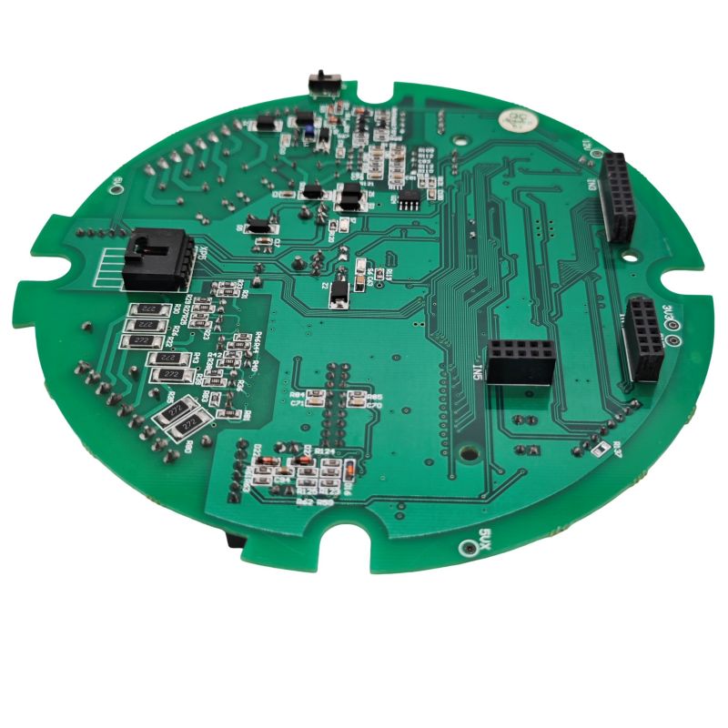
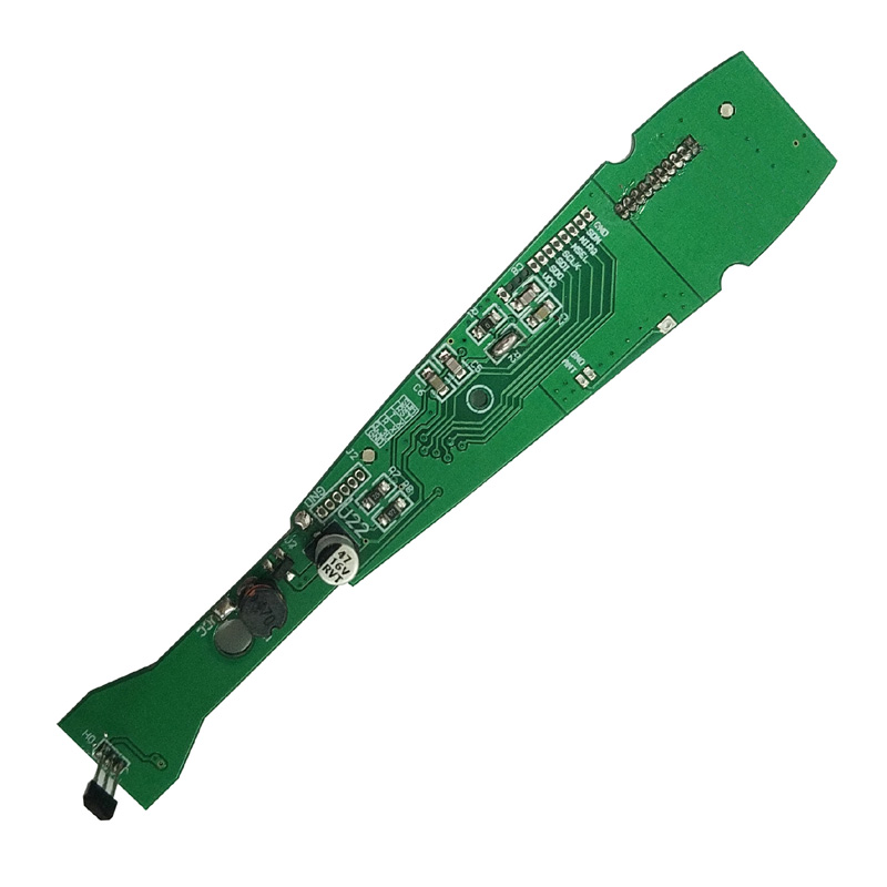
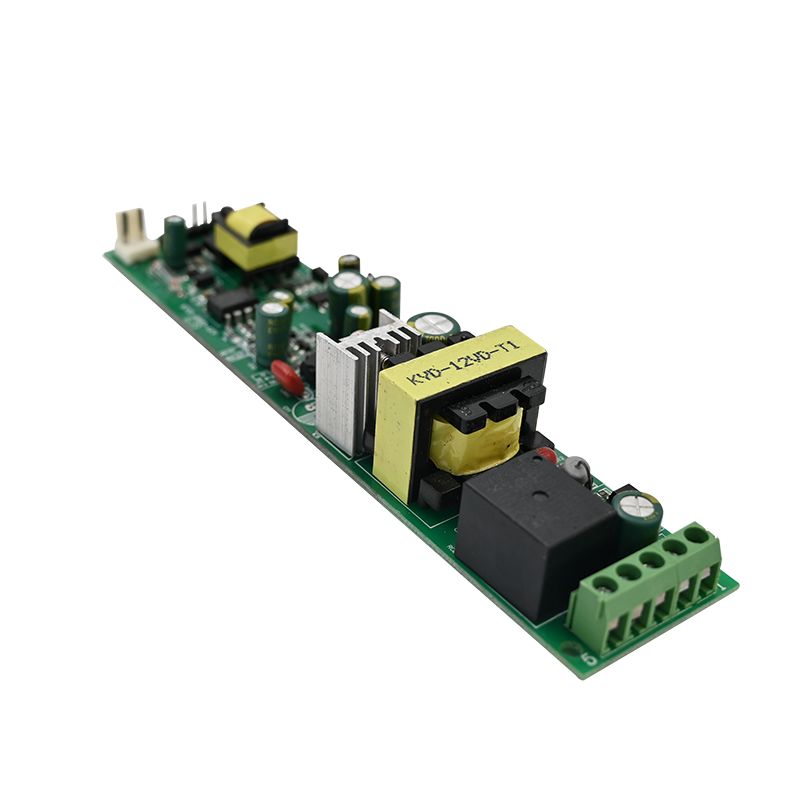
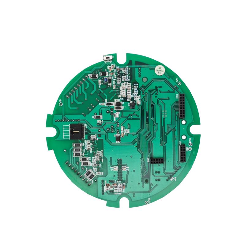
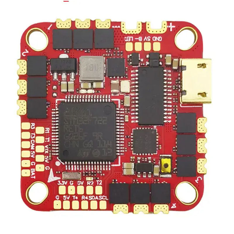
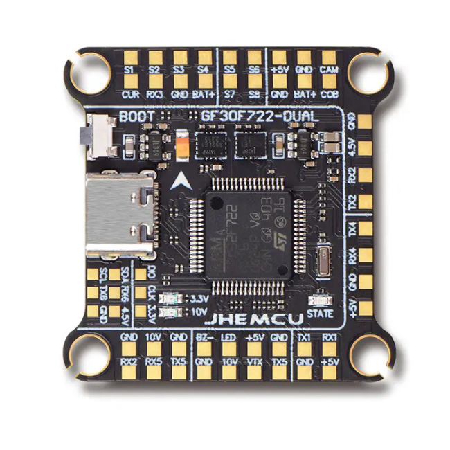
Unixplore Electronics BMS PCBA is a professional battery management circuit board solution designed for lithium battery applications. As a China BMS PCBA Manufacturer, Factory, Unixplore Electronics provides PCB assembly solutions for EV, energy storage, and e-mobility systems.
Send Inquiry
Product Description
With 20 years of failure analysis across EV, energy storage, and e-mobility sectors, I have documented exactly what separates a 10-year BMS from a 6-month hazard. This guide provides engineering specifications, layout rules, and verification methods based on real field returns.
What a BMS PCBA Must Do
A BMS PCBA monitors, protects, and balances lithium cells. Four functions are non-negotiable:
Over-Voltage Protection (OVP): Cut off charge at 4.25V per cell (Li-ion).
Under-Voltage Protection (UVP): Cut off discharge at 2.5V to 3.0V per cell.
Over-Current Protection (OCP): Fast trip (µs range) for short circuits.
Cell Balancing: Passive or active equalization across series cells.
Missing any of these turns the assembly into a liability.
Core Technical Parameters
The following values represent industry minimums for safe operation. Always exceed these for automotive or stationary storage.
Voltage & Current Ratings
| Parameter | 3S to 7S (Light EV) | 8S to 16S (Energy Storage) | 24S+ (High Voltage) |
| Max Continuous Discharge | 20A to 60A | 60A to 200A | 200A+ |
| Peak Current (10 sec) | 80A to 150A | 200A to 400A | 500A+ |
| Charge Current | 5A to 20A | 20A to 50A | 50A+ |
| Cell Voltage Accuracy | ±10mV | ±5mV | ±3mV (premium AFE required) |
| Temperature Measurement Points | 2 to 4 | 4 to 8 | 8 to 12 |
Protection Trip Points (Per Cell for Li-Ion)
| Protection Type | Min Trip | Typical Trip | Max Trip |
| Over-Voltage | 4.20V | 4.25V | 4.30V |
| Over-Voltage Release | 4.05V | 4.10V | 4.15V |
| Under-Voltage | 2.80V | 2.50V | 2.30V |
| Under-Voltage Release | 3.00V | 3.10V | 3.20V |
| Charge Over-Current | 1.2x rated | 1.5x rated | 2.0x rated |
| Discharge Over-Current | 1.5x rated | 2.0x rated | 2.5x rated |
| Short Circuit | 3x to 5x rated | Within 300µs | Within 100µs |
Quiescent Current (Sleep Mode)
| Battery Type | Acceptable Sleep Current | High-Performance Target |
| Li-ion (portable) | <20µA | <10µA |
| LiFePO4 (stationary) | <50µA | <30µA |
| EV / High power | <100µA | <50µA |
PCBA Layout Rules for Reliability
Most BMS failures originate on the PCB, not the ICs. Follow these 12 rules.
Kelvin Sense Traces for Cell Voltages
Never route cell sense traces through high-current paths.
Each cell tap requires a dedicated trace (0.2mm to 0.3mm) from the connector directly to the AFE (Analog Front End) pin.
No branching: Do not share sense traces between cells.
High-Current Path Design
Copper weight: 2 oz minimum for 20A to 50A. 4 oz for 50A to 100A.
Parallel layers: Use multiple layers in parallel for currents above 60A.
Solder mask opening: Expose the copper and add additional solder to increase cross-section. This reduces resistance by 30% to 40%.
Sense Resistor Placement
Four-wire (Kelvin) connection: The sense resistor must have dedicated voltage sensing traces from its pads.
Placement: Within 10mm of the AFE differential input pins.
Trace matching: Sense traces must be equal length and parallel for current measurement accuracy.
Thermal Management for FETs
Copper area: Each MOSFET drain pad requires a 300mm² to 500mm² copper plane.
Thermal vias: 9 to 12 vias (0.3mm diameter) under each FET thermal pad.
Via filling: Filled and capped vias are mandatory for soldering reliability.
Component Spacing for Voltage Isolation
| Voltage Level | Creepage Distance (Min) | Clearance (Min) |
| Up to 60V (16S Li-ion) | 0.5mm | 0.2mm |
| 60V to 150V | 1.5mm | 1.0mm |
| 150V to 300V | 3.0mm | 2.0mm |
Ground Plane Splitting
High-current ground (power path): Thick traces, no splits.
Low-current analog ground (AFE, sense): Star connect to battery negative terminal.
Connection point: Join analog and power ground at a single point near the sense resistor.
Component Selection Checklist
A reliable BMS PCBA starts with the right bill of materials.
Need the complete BOM and design checklist for your BMS project?
Download Free BMS PCBA Checklist →
Analog Front End (AFE)
| Feature | Minimum Requirement | Preferred |
| Cell Voltage Measurement Accuracy | ±10mV | ±3mV |
| Built-in Balancing FETs | 50mA to 100mA | External balancing for >100mA |
| Open Wire Detection | Yes | Yes |
| Temperature Channels | 3 | 5+ |
Recommended AFE families: Texas Instruments BQ769x2 (up to 16S), Analog Devices LTC681x (high voltage), NXP MC33771C (automotive).
Power MOSFETs
Voltage rating: At least 1.5x maximum pack voltage. For 16S Li-ion (67V max), use 100V FETs.
Current rating: 2x continuous discharge current at 100°C junction temperature.
Parallel FETs: For 100A+, use 4 to 8 FETs in parallel. Gate traces must be equal length to ensure simultaneous switching.
Current Sense Resistor
| Parameter | Value | Reason |
| Resistance | 0.5mΩ to 2mΩ | Minimizes power loss |
| Tolerance | ±1% or better | Affects over-current trip accuracy |
| Temperature Coefficient | ±50ppm/°C maximum | Prevents drift with heat |
| Material | Metal alloy (Manganin) | Low inductance for short circuit detection |
Passive Components for Reliability
Capacitors: X7R or X5R dielectric only. Never use Y5V or Z5U near AFE pins.
Resistors for sense inputs: 1kΩ to 10kΩ series resistors on every cell sense line. Limits current during fault events.
TVS diodes: Bi-directional 5V to 6V across each cell input. Protects AFE from ESD and wire harness spikes.
Manufacturing and Inspection Requirements
A well-designed BMS PCBA fails in assembly if these steps are ignored.
| Process | Requirement | Inspection Method |
| Solder Paste Stencil | 0.12mm to 0.15mm thickness for AFE and FET pads | SPI (Solder Paste Inspection) |
| Reflow Profile | Peak 240°C to 250°C (lead-free) | Profiler data per batch |
| AOI (Automated Optical Inspection) | 100% coverage on passive components and FET orientation | AOI machine logs |
| X-Ray Inspection | FET thermal pad voids under 25% | X-ray system |
| ICT (In-Circuit Test) | All voltage dividers, FET gates, and sense resistors | ICT fixture |
| Conformal Coating | Acrylic or silicone, 0.03mm minimum thickness | UV light inspection |
BMS PCBA FAQs
Below are three technical questions from engineers and battery pack assemblers.
Q1: Why does my BMS PCBA keep triggering false over-current protection during normal motor start-up?
A: You have an inrush current problem combined with a too-fast OCP filter. Here is the engineering fix:
Most BMS AFEs have a configurable over-current protection delay (typically 100µs to 1ms). Motor start-up (especially brushless DC motors) draws 5x to 8x rated current for 1ms to 5ms.
Step 1 - Measure actual inrush: Use an oscilloscope with a current probe across the sense resistor. Record the peak current and duration during the worst-case start-up (cold motor, low battery).
Step 2 - Adjust AFE registers: Increase the over-current delay to 2ms to 5ms. Keep the short-circuit delay at 100µs (this protects against dead shorts).
Step 3 - Hardware filter tuning: Add a 100nF capacitor between the AFE current sense pins. This creates a 10µs to 20µs RC filter that ignores very short spikes.
Step 4 - If still tripping: Your sense resistor is too large. A 2mΩ resistor produces 200mV at 100A. Switch to 1mΩ or 0.5mΩ to increase the headroom before the over-current comparator trips.
Warning: Do not disable OCP. False trips are annoying. A fire is permanent.
Q2: How do I design a BMS PCBA that balances a 16S LiFePO4 pack with 200Ah cells?
A: Standard integrated balancing FETs (50mA to 100mA) will take 80 to 160 hours to balance 200Ah cells. That is unusable. You need external passive balancing or active balancing.
Option A - External Passive Balancing (Cost Effective):
Use an AFE that controls external balancing FETs (e.g., BQ76952 with external N-channel FETs).
Component selection per cell:
Balancing resistor: 10Ω to 22Ω, 5W to 10W (metal oxide or wirewound).
Balancing FET: 60V, 5A, Rds(on) < 50mΩ.
Balancing current: 200mA to 500mA. (Using 10Ω resistor at 3.3V cell = 330mA.)
PCB thermal requirement: Each resistor dissipates 1W to 1.5W. Requires 500mm² copper area per resistor.
Option B - Active Balancing (High Performance):
Use an active balancer IC (e.g., Analog Devices LTC3300 or Texas Instruments BQ79616).
Topology: Capacitive or transformer based.
Balancing current: 1A to 5A per cell.
Efficiency: 85% to 92%.
PCB complexity: Requires 6 to 8 layers, careful isolation between cells.
Recommendation for 200Ah cells: Use external passive balancing at 300mA to 500mA. Add a heatsink over the balancing resistor array. Active balancing only if cycle life is critical and budget allows 2x higher PCBA cost.
Q3: What tests must a BMS PCBA pass before I approve it for production?
A: Require five tests. Do not skip any.
| Test | Method | Pass / Fail Criteria |
| 1. Cell Voltage Measurement Accuracy | Apply precision 0V to 5V to each cell input via resistor divider. Compare AFE reading to DMM (6.5 digit). | ±5mV maximum error across all cells at 25°C. ±10mV from -20°C to +60°C. |
| 2. Over-Voltage / Under-Voltage Trip | Slowly ramp cell voltage up and down. Record AFE trip and release points. | Trip within ±10mV of programmed value. Hysteresis between 0.05V and 0.15V. |
| 3. Over-Current Trip Test | Apply pulsed current from electronic load. Increase in steps. Record trip point and response time. | Trip current within ±5% of programmed value. Trip time under 1ms for short circuit. |
| 4. Balancing Function | Force one cell 50mV higher than others. Enable balancing for 1 hour. | Cell voltages equalize to within 15mV. FET temperature rise under 40°C. |
| 5. Sleep Mode Current | Remove all external power. Measure current draw from battery pack after 10 minutes. | Under 50µA for LiFePO4 stationary. Under 20µA for portable Li-ion. |
Hot Tags: BMS PCBA, China, Manufacturers, Suppliers, Factory, Customized, Cheap, Quality, Advanced, CE, 1 Year Warranty, Price
Related Category
Home Appliance PCBA
Industrial Control PCBA
Automobile PCBA
Consumer Electronics PCBA
Medical Equipment PCBA
Security System PCBA
Healthcare PCBA
LED Lighting PCBA
IoT PCBA
Electric Gardening Tool PCBA
Send Inquiry
Please Feel free to give your inquiry in the form below. We will reply you in 24 hours.