- English
- Español
- Português
- русский
- Français
- 日本語
- Deutsch
- tiếng Việt
- Italiano
- Nederlands
- ภาษาไทย
- Polski
- 한국어
- Svenska
- magyar
- Malay
- বাংলা ভাষার
- Dansk
- Suomi
- हिन्दी
- Pilipino
- Türkçe
- Gaeilge
- العربية
- Indonesia
- Norsk
- تمل
- český
- ελληνικά
- український
- Javanese
- فارسی
- தமிழ்
- తెలుగు
- नेपाली
- Burmese
- български
- ລາວ
- Latine
- Қазақша
- Euskal
- Azərbaycan
- Slovenský jazyk
- Македонски
- Lietuvos
- Eesti Keel
- Română
- Slovenski
- मराठी
- Srpski језик

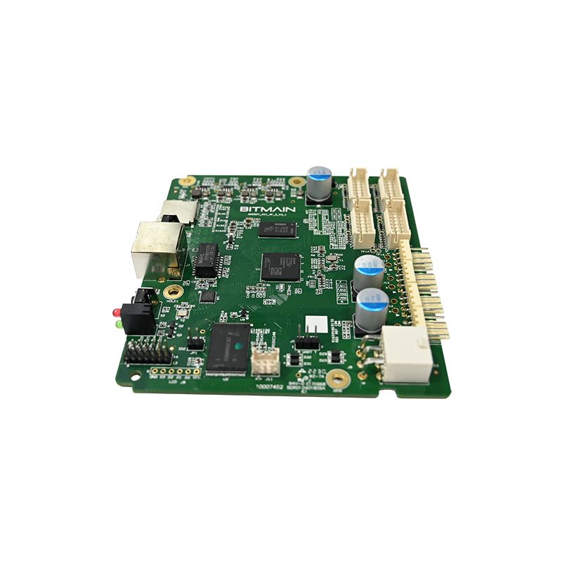
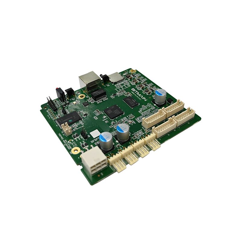
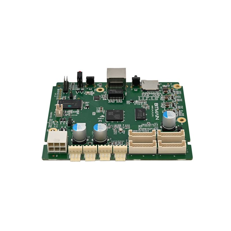
Motion Sensor PCBA
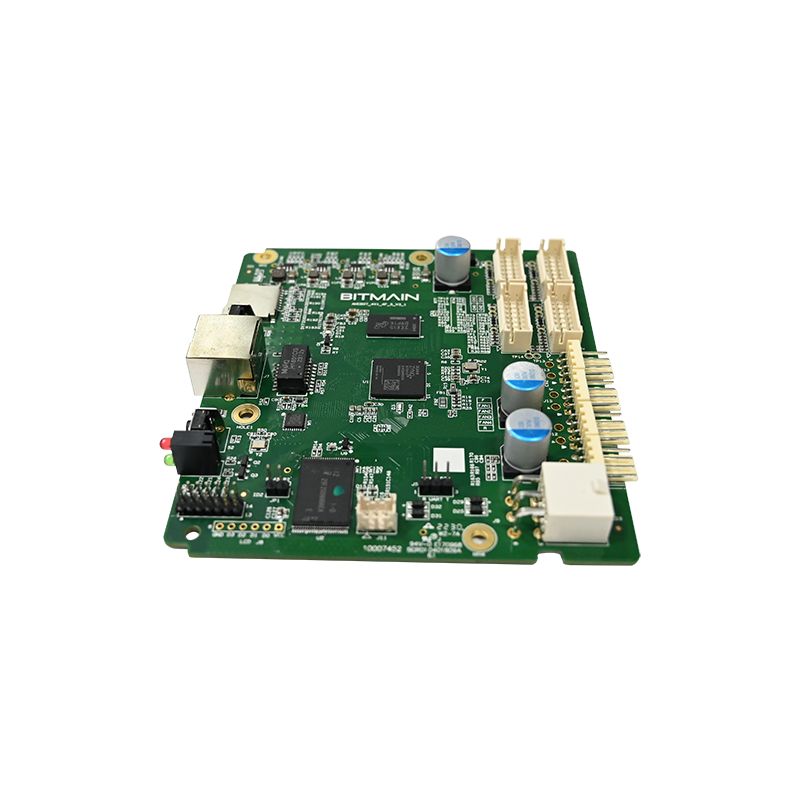
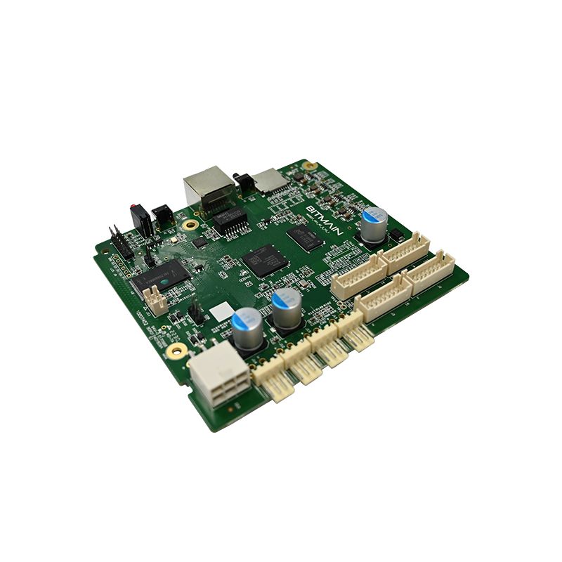
Motion Sensor PCBA is a high-sensitivity intelligent motion detection circuit board designed for PIR sensors, microwave motion detectors, smart lighting systems, occupancy sensing devices, automatic doors, and security alarm equipment. As a professional Motion Sensor PCBA manufacturer and OEM PCB assembly supplier, UNIXPLORE provides low power consumption, fast response, anti-false-trigger filtering, and stable signal processing solutions for commercial and industrial motion sensing applications.
Send Inquiry
Product Description
What Is a Motion Sensor PCBA?
A motion sensor PCBA is a printed circuit board assembly designed specifically to detect movement using infrared, microwave, or ultrasonic transducers. Unlike general-purpose PCBA, motion sensor boards require low power consumption, fast wake-from-sleep response, and noise filtering to avoid false triggers.
Engineers select a motion sensor PCBA based on three parameters: detection range, output signal type, and operating current. The wrong choice leads to frequent false alarms or missed detections.
Core Components of a Motion Sensor PCBA
Every motion sensor PCBA contains these five functional blocks:
· Sensor element – PIR (pyroelectric), microwave Doppler, or ultrasonic transducer
· Analog front end – Operational amplifier with bandpass filter
· Comparator – Threshold detector with hysteresis
· Timing logic – Adjustable hold time and lockout period
· Output stage – Relay, transistor, or logic-level signal
Typical Applications
|
Application |
Preferred Sensor Type |
Key Requirement |
|
Security lighting |
PIR |
Wide angle, low cost |
|
Occupancy detection |
PIR + microwave |
No dead zones |
|
Automatic doors |
Microwave |
Insensitive to temperature |
|
Smart home PIR |
PIR |
Ultra-low standby current |
|
Industrial safety |
Ultrasonic |
Works in dusty environments |
Detailed Technical Parameters of This Motion Sensor PCBA
The following specifications represent a typical high-performance motion sensor PCBA used in commercial and residential security products.
Electrical Characteristics
|
Parameter |
Minimum |
Typical |
Maximum |
Unit |
|
Operating voltage |
3.0 |
5.0 |
24 |
VDC |
|
Standby current |
15 |
20 |
35 |
µA |
|
Active current (LED on) |
2.5 |
3.0 |
5.0 |
mA |
|
Output load (relay) |
– |
– |
10 |
A @ 250VAC |
|
Output load (transistor) |
– |
– |
100 |
mA |
|
Warm-up time |
– |
30 |
60 |
seconds |
Detection Performance
|
Parameter |
Value |
Condition |
|
Detection range |
8-12 meters |
25°C ambient |
|
Detection angle |
110-140 degrees |
Fresnel lens type B |
|
Motion speed sensitivity |
0.3 to 2.0 m/s |
Adjustable potentiometer |
|
Hold time |
5 seconds to 10 minutes |
Four DIP switch settings |
|
Lockout time |
0 to 10 seconds |
Optional after trigger |
Physical and Environmental Specifications
· Board dimensions – 32mm x 28mm (standard) or custom
· Mounting holes – Two 3mm diameter, 25mm center-to-center
· Operating temperature – -20°C to +70°C
· Storage temperature – -40°C to +85°C
· Humidity tolerance – 95% RH non-condensing
· Conformal coating – Optional (for outdoor or humid use)
Adjustable Settings (DIP Switch or Jumper)
Most motion sensor PCBA designs include user-configurable parameters:
|
Setting # |
Function |
Options |
|
1 |
Detection sensitivity |
High / Medium / Low |
|
2 |
Hold time |
5s / 30s / 3min / 10min |
|
3 |
Light threshold (day/night) |
Disable / 10 Lux / 50 Lux |
|
4 |
Output type |
Normally open / Normally closed |
How This Motion Sensor PCBA Compares to Competing Designs
Not all motion sensor PCBA boards perform equally in real-world conditions. The table below shows critical differences.
|
Feature |
Standard Board |
This Motion Sensor PCBA |
|
Standby current |
50-100 µA |
20 µA typical |
|
False trigger filtering |
Single comparator |
Dual window comparator |
|
Temperature compensation |
None |
±10% over full range |
|
Output protection |
Diode only |
TVS + relay snubber |
|
PCB thickness |
1.0mm |
1.6mm (reduces flex) |
Motion Sensor PCBA FAQ – Engineering Answers
These three questions are asked weekly by hardware engineers, integrators, and procurement specialists evaluating motion sensor PCBA solutions.
Question 1: What is the difference between PIR, microwave, and dual-tech motion sensor PCBA designs – and which one should I choose?
Answer: A PIR (passive infrared) motion sensor PCBA detects changes in infrared radiation from moving bodies. It consumes very low power (15-30µA standby) but is sensitive to temperature gradients and can false-trigger from HVAC vents or sunlight. A microwave motion sensor PCBA emits low-power RF (typically 5.8GHz or 10.525GHz) and measures Doppler shift. It detects through plastic enclosures and ignores temperature, but consumes higher current (15-25mA) and can penetrate walls, causing false detection from adjacent rooms. A dual-tech motion sensor PCBA contains both PIR and microwave sensors, and triggers only when both detect motion. This eliminates almost all false alarms but increases cost and standby current (2-5mA). Selection guide: For battery-powered outdoor lights, choose PIR-only. For indoor occupancy detection where false triggers are unacceptable, choose dual-tech. For automatic doors where speed matters more than power use, choose microwave-only. Most commercial security motion sensor PCBA designs use PIR with advanced signal filtering as the best balance of cost, power, and reliability.
Question 2: How do I adjust the detection range and hold time on this motion sensor PCBA, and can these settings be changed without removing the board from its enclosure?
Answer: This motion sensor PCBA provides three methods of adjustment. First, onboard potentiometers: one labeled “SENS” (sensitivity) adjusts detection range from 3 meters (fully counterclockwise) to 12 meters (fully clockwise). A second labeled “TIME” adjusts hold time from 5 seconds to 10 minutes. Second, DIP switches: most boards include a 4-position switch for coarse settings of hold time, light threshold, and output polarity. Third, for remote adjustment, some motion sensor PCBA designs include a digital input that accepts external potentiometers or 0-10V control signals. For adjustments without opening the enclosure, specify a motion sensor PCBA with a remote control receiver (38kHz IR or 433MHz RF) – this adds approximately $1.50 to the BOM cost. Without remote adjustment, you must open the enclosure and use a small screwdriver to turn the potentiometers. Always adjust sensitivity after mounting in its final location, because the surrounding walls and floor material affect detection range. Start with sensitivity at 50% and increase only if coverage gaps exist.
Question 3: What is the typical false trigger rate for this motion sensor PCBA, and how does temperature compensation reduce false alarms?
Answer: In a properly installed application (no direct sunlight on the lens, no heat vents within 2 meters, no large glass windows reflecting moving traffic), this motion sensor PCBA achieves a false trigger rate of less than one event per 200 detections. Without temperature compensation, a PIR motion sensor PCBA can false-trigger when ambient temperature approaches human skin temperature (approximately 37°C or 98°F). At 30°C room temperature, the signal-to-noise ratio drops by 60% compared to 20°C. This motion sensor PCBA includes an onboard thermistor connected to a compensation circuit that increases gain by 2.5% for every 1°C rise above 25°C. At 35°C, gain is 25% higher than at 25°C, restoring detection sensitivity. The compensation also reduces gain at low temperatures (below 10°C) to prevent false triggers from cold drafts. Field data from motion sensor PCBA installations in Middle Eastern climates (outdoor temperatures reaching 45°C) show a 78% reduction in nuisance alarms when temperature compensation is enabled versus disabled. Always enable compensation for outdoor or unconditioned indoor spaces.
Installation Best Practices for Motion Sensor PCBA
Even the best motion sensor PCBA performs poorly if installed incorrectly. Follow these guidelines.
Mounting Height and Position
· Recommended height – 1.8 to 2.2 meters (shoulder to head level)
· Below 1.5 meters – Misses torso motion, detects pets only
· Above 2.5 meters – Reduced ground coverage, creates dead zones directly below
Avoid These False Trigger Sources
|
Source |
Mitigation |
|
Direct sunlight |
Use opaque Fresnel lens shield |
|
HVAC vents |
Orient sensor away from airflow |
|
Moving curtains |
Secure curtains or disable sensitivity |
|
Pet movement |
Use pet-immune lens (masking lower zone) |
Wiring Guidelines
· Use twisted pair for output signal runs longer than 10 meters
· Keep AC power wires at least 30cm from motion sensor PCBA
· Add a 100nF capacitor across power input if switching noisy loads (relays, contactors)
Testing Your Motion Sensor PCBA Before Installation
A bench test catches 90% of setup errors. Follow this sequence.
Bench Test Procedure
1. Apply power and wait 60 seconds for warm-up
2. Confirm LED blinks approximately once every 10 seconds (indicates standby)
3. Walk across the field of view at 3 meters distance
4. Verify LED turns on and output changes state
5. Mark the time until LED turns off (should match hold time setting)
6. Repeat with slow creep (0.2 m/s) and fast run (2 m/s)
Failures and Causes
|
Symptom |
Likely Cause |
|
No detection at any distance |
Defective sensor element or missing lens |
|
Continuous triggering |
Sensitivity too high or mounting vibrations |
|
Short range |
Low supply voltage or contaminated lens |
|
Works once then stops |
Output load shorted or over-current |
Summary – Key Specifications Reference
For quick reference, keep this specification block available during design and procurement.
Motion Sensor PCBA – Default Configuration
· Voltage: 5-24V DC
· Standby current: 20µA typical
· Detection range: 8-12 meters
· Detection angle: 120 degrees
· Hold time: adjustable 5s to 10min
· Output: Relay (10A) or transistor (100mA)
· Operating temperature: -20°C to +70°C
· Certifications: Compliant with ISO9001 and RoHS standards
Hot Tags: Motion Sensor PCBA, China, Manufacturers, Suppliers, Factory, Customized, Cheap, Quality, Advanced, CE, 1 Year Warranty, Price
Related Category
Home Appliance PCBA
Industrial Control PCBA
Automobile PCBA
Consumer Electronics PCBA
Medical Equipment PCBA
Security System PCBA
Healthcare PCBA
LED Lighting PCBA
IoT PCBA
Electric Gardening Tool PCBA
Send Inquiry
Please Feel free to give your inquiry in the form below. We will reply you in 24 hours.