- English
- Español
- Português
- русский
- Français
- 日本語
- Deutsch
- tiếng Việt
- Italiano
- Nederlands
- ภาษาไทย
- Polski
- 한국어
- Svenska
- magyar
- Malay
- বাংলা ভাষার
- Dansk
- Suomi
- हिन्दी
- Pilipino
- Türkçe
- Gaeilge
- العربية
- Indonesia
- Norsk
- تمل
- český
- ελληνικά
- український
- Javanese
- فارسی
- தமிழ்
- తెలుగు
- नेपाली
- Burmese
- български
- ລາວ
- Latine
- Қазақша
- Euskal
- Azərbaycan
- Slovenský jazyk
- Македонски
- Lietuvos
- Eesti Keel
- Română
- Slovenski
- मराठी
- Srpski језик

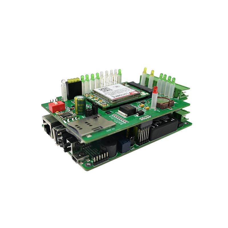
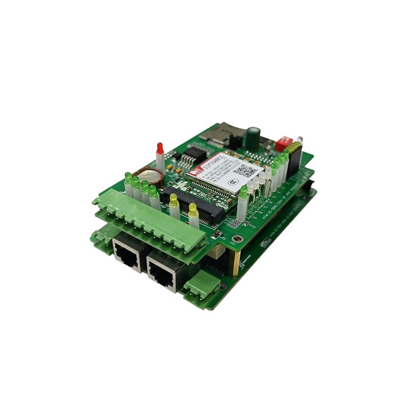
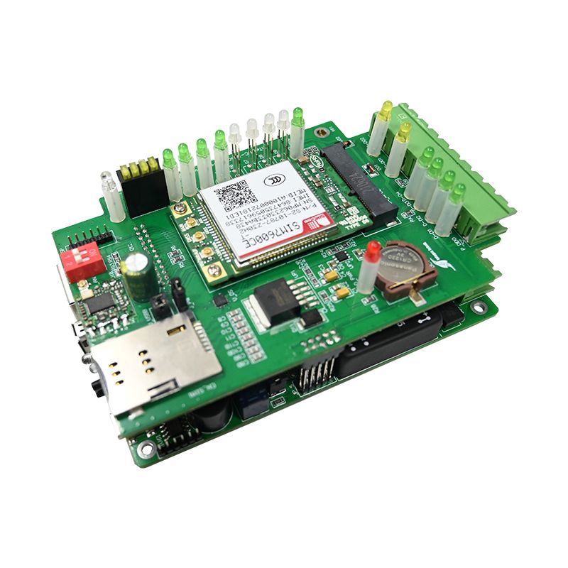
Access Control PCBA
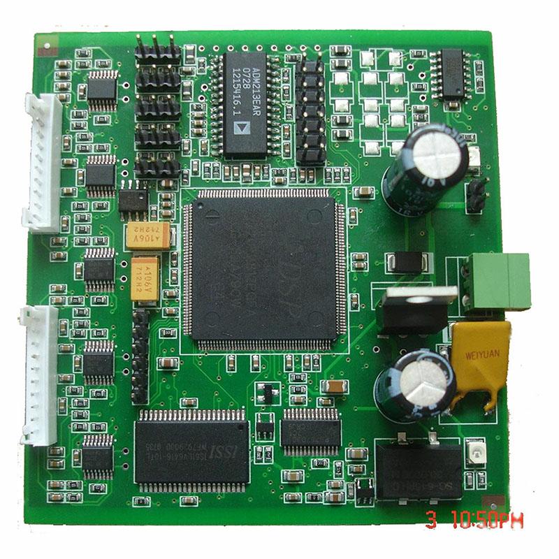
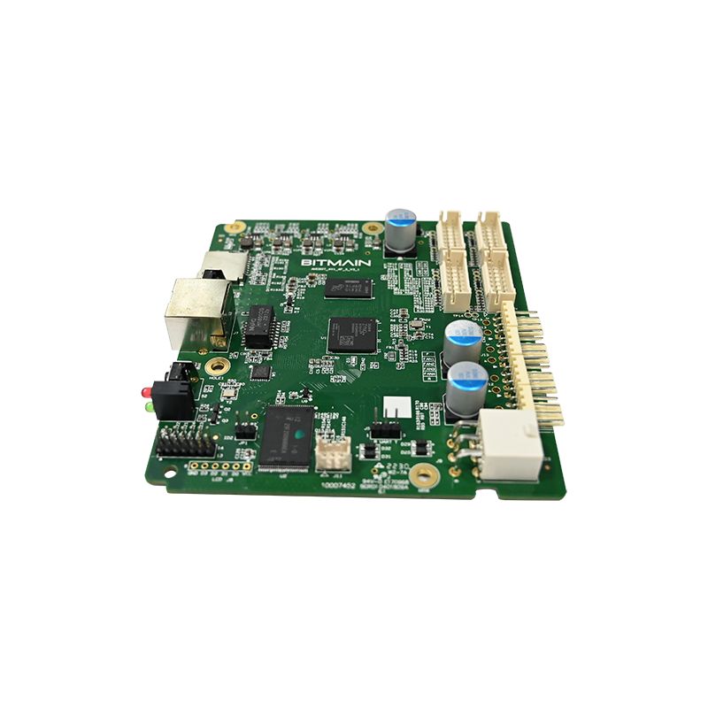
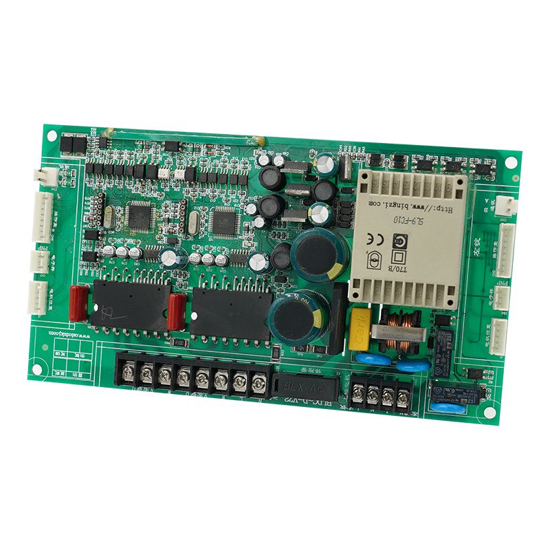
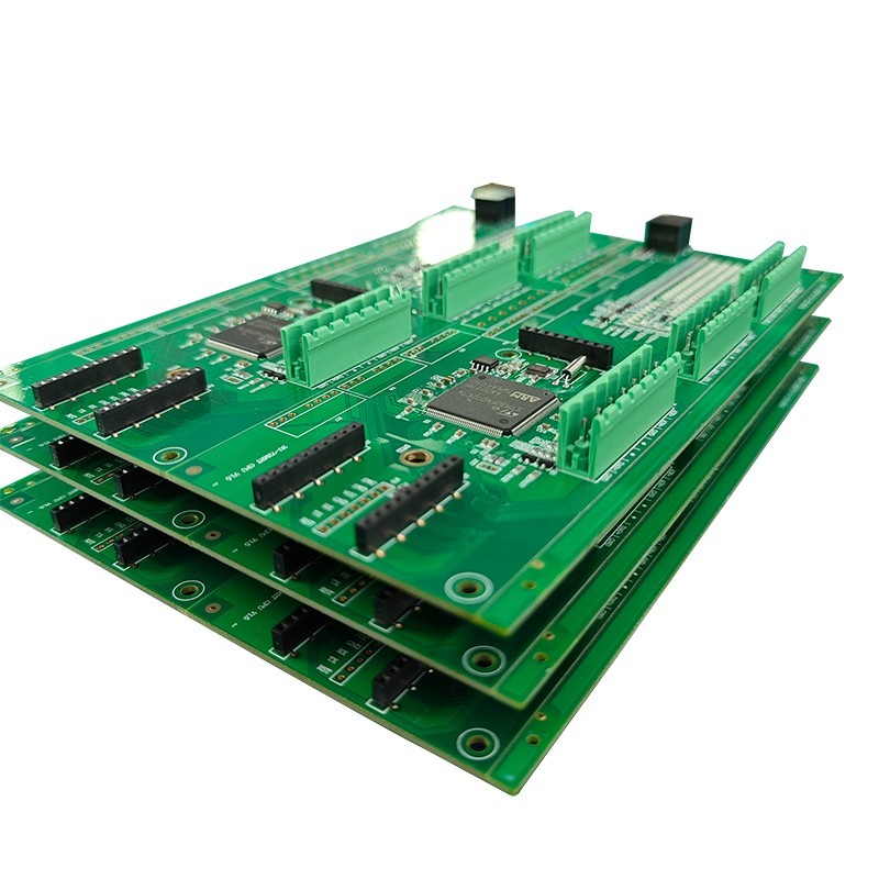
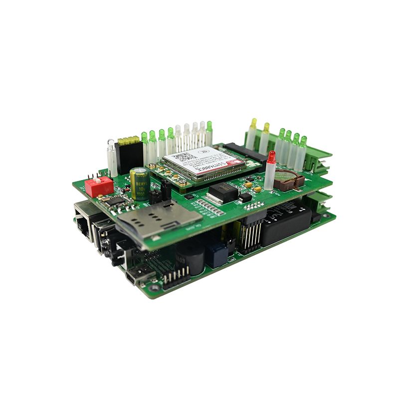
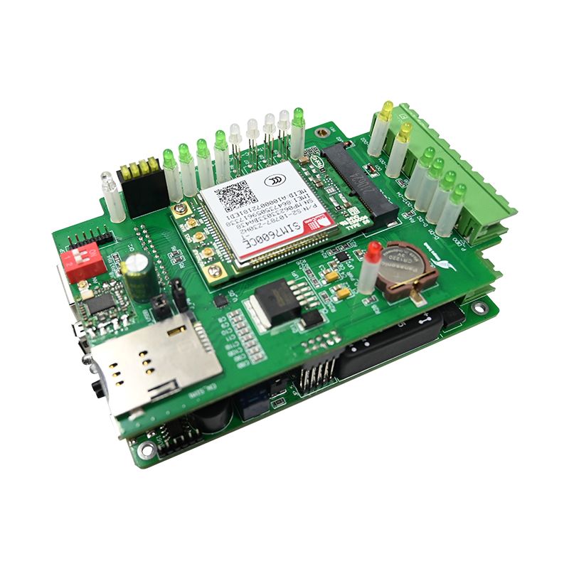
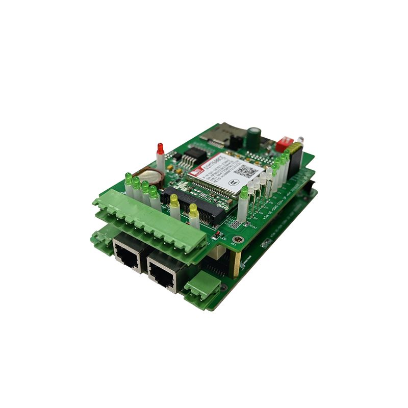
UNIXPLORE Access Control PCBA is a high-performance security access control circuit board designed for RFID access systems, biometric door controllers, smart lock systems, elevator access management, and commercial security equipment manufacturers. As a professional Access Control PCBA manufacturer and OEM PCB assembly supplier, UNIXPLORE provides stable, secure, and customizable access control PCB solutions with Wiegand and OSDP communication support, fast credential authentication, anti-tamper protection, and industrial-grade reliability.
Send Inquiry
Product Description
UNIXPLORE Access Control PCBA is developed for security equipment brands, access control system integrators, and intelligent building solution providers seeking reliable and scalable electronic access control solutions. This commercial-grade access control PCBA combines fast authentication processing, stable relay control, encrypted communication, and flexible offline management into a compact and durable PCB platform.
What Is an Access Control PCBA?
An access control PCBA is the electronic brain inside card readers, keypads, biometric scanners, and door controllers. It processes credential data, makes authentication decisions, and triggers lock actuators. Unlike general-purpose boards, a PCBA must handle security-grade encryption, fail-safe relay logic, and uninterrupted power during brief outages.
Selecting the wrong access control PCBA leads to door strikes that fail to latch, credentials that take seconds to verify, or complete system lockups during high traffic periods.
Core Functions of an Access Control PCBA
- Credential reading – Wiegand, OSDP, or serial input from RFID/hid card readers
- Authentication logic – Onboard database (offline) or relay to host controller
- Relay control – Dry contact outputs for magnetic locks or electric strikes
- Input monitoring – Door position sensor (reed switch) and request-to-exit (REX) button
- Anti-tamper detection – Enclosure open sensor and memory tamper protection
Typical Applications
| Application | Typical User Count | Key Requirement |
|---|---|---|
| Office door controller | 50-500 users | Schedule-based access |
| Apartment intercom | 100-1000 users | Two-way audio + unlock |
| Server room lock | 10-50 users | Dual authentication |
| Turnstile gate | 1000+ users | Fast relay cycling (0.5 sec) |
| Elevator access control | 10-100 floors | Floor-by-floor permission |
Detailed Technical Parameters
The following specifications represent a commercial-grade access control PCBA suitable for offices, apartments, and industrial facilities.
Electrical Characteristics
| Parameter | Minimum | Typical | Maximum | Unit |
|---|---|---|---|---|
| Operating voltage | 9 | 12 | 24 | VDC |
| Standby current | 40 | 60 | 100 | mA |
| Active current (relay energized) | 120 | 150 | 200 | mA |
| Relay contact rating | 3 | 5 | 10 | A @ 30VDC |
| Reader input power | – | 12 | – | VDC at 150mA max |
| Tamper output | – | – | 100 | mA (open collector) |
Input and Output Interfaces
| Interface Type | Quantity | Signal Format |
|---|---|---|
| Wiegand reader input | 1 or 2 | 26-bit, 34-bit (D0/D1) |
| OSDP reader input | 1 | RS-485 (up to 4 readers addressable) |
| Door position sensor | 1 | Dry contact (N/O or N/C) |
| REX button | 1 | Dry contact (N/O) |
| Auxiliary input | 1 | Programmable (fire alarm interlock) |
| Lock relay | 1 | Form C (COM, N/O, N/C) |
| Auxiliary relay | 1 | Optional (alarm or strobe) |
Memory and User Capacity
| Parameter | Standard Model | Extended Model |
|---|---|---|
| User capacity (offline mode) | 1,000 | 10,000 |
| Event buffer size | 10,000 events | 50,000 events |
| Scheduled time zones | 8 | 32 |
| Holiday groups | 16 | 64 |
Physical and Environmental
- Board dimensions – 85mm x 55mm (standard) or 100mm x 70mm (with enclosure)
- Mounting – Four 3.5mm holes for standoffs
- Operating temperature – -20°C to +65°C
- Storage temperature – -40°C to +85°C
- Humidity tolerance – 10% to 90% RH (non-condensing)
- Battery backup – Optional 3.7V Li-ion or 12V lead-acid charging circuit
Security Features
- Encryption – AES-128 for OSDP communication
- Tamper detection – Enclosure open triggers relay lockout and alarm output
- Watchdog timer – Automatic reset after 5 seconds of processor lockup
- Flash memory protection – Checksum verification on boot
How This Access Control PCBA Compares
| Feature | Basic Controller | This Access Control PCBA |
|---|---|---|
| Reader input | Wiegand only | Wiegand + OSDP |
| User capacity | 500 | 1,000 (expandable to 10,000) |
| Relay hold time | Fixed 5 seconds | Adjustable 1-60 seconds |
| Fire alarm interlock | None | Dedicated input with fail-safe override |
| Event logging | 1,000 events | 10,000 events with time stamp |
| Anti-passback support | No | Yes (hard or soft) |
Access Control PCBA FAQ
These three questions are asked by security system integrators, facility managers, and hardware engineers evaluating access control PCBA solutions.
Question 1: What is the difference between fail-secure and fail-safe relay configurations on an access control PCBA, and which should I use?
Answer: The difference determines whether doors lock or unlock during a power outage. Fail-secure (also called power-to-open) means the relay must be energized to unlock the door. When power is lost, the relay returns to its resting state, which keeps the door locked. This is used for security doors, server rooms, and cash handling areas where keeping intruders out is more important than easy exit. Fail-safe (power-to-lock) means the relay must be energized to lock the door. When power is lost, the door automatically unlocks. This is required by fire codes for emergency exits, stairwell doors, and any egress path where people must escape during a power failure. Most access control PCBA boards provide a dry contact relay configured as Form C (COM, N/O, N/C). For fail-secure, connect the lock to the N/O terminal. For fail-safe, connect the lock to the N/C terminal. Always verify local fire codes before selecting – NFPA 101 requires fail-safe on all egress doors in commercial buildings. For doors requiring both security and fire compliance, use a fail-safe lock plus a battery backup panel that keeps the access control PCBA powered for 4-8 hours after mains failure.
Question 2: Can this access control PCBA work offline without a network connection, and how many users can it store locally?
Answer: Yes. This PCBA operates fully offline in standalone mode. All user credentials, access schedules, and event logs are stored in onboard flash memory. The standard configuration holds 1,000 users with 10,000 event logs at no additional cost. An extended version (field-upgradable via firmware) holds 10,000 users and 50,000 events. Offline operation requires a programming device to initially load users – either a dedicated master card (first card programmed defines administrator privileges), a wired keypad connected to an auxiliary input, or a temporary laptop connection via the configuration port (TTL or RS-232). Once programmed, the access control PCBA makes authentication decisions locally in under 50 milliseconds. No cloud, no host PC, no Ethernet cable is required. This makes offline PCBA designs ideal for remote gates, construction trailers, and small offices where running network cabling is impractical. To retrieve event logs from an offline board, you must connect a laptop or use a portable data transfer device. Real-time monitoring requires a networked access control PCBA with Ethernet or Wi-Fi.
Question 3: How do I wire a Wiegand reader to this access control PCBA, and what is the maximum cable distance?
Answer: The Wiegand interface uses three active signals: Data 0 (D0), Data 1 (D1), and ground (GND). Some readers also require +12V power. Follow this wiring table:
| Reader Terminal | Access Control PCBA Terminal |
|---|---|
| Red (+12V) | +12V output (reader power) |
| Black (GND) | GND |
| Green (D0) | WIEGAND_D0 |
| White (D1) | WIEGAND_D1 |
| Violet (LED control, optional) | Aux output (programmable) |
Maximum cable distance for Wiegand at 12V depends on wire gauge and cable capacitance:
| Wire Gauge | Shielded Twisted Pair | Unshielded | Maximum Distance |
|---|---|---|---|
| 22 AWG | Yes | No | 150 meters (500 feet) |
| 24 AWG | Yes | No | 100 meters (330 feet) |
| 24 AWG | No | Yes | 50 meters (165 feet) |
Use stranded, shielded, twisted-pair cable with drain wire. Connect the shield to earth ground at the access control PCBA end only (never at the reader) to avoid ground loops. For distances exceeding these limits, install a Wiegand repeater or switch to OSDP (RS-485), which reliably reaches 1,200 meters (4,000 feet). Always test with a long cable on the bench before final installation – signal degradation can cause intermittent card reads that are difficult to debug on site.
Installation Best Practices for Access Control PCBA
Even a high-quality access control PCBA fails if installed incorrectly. Follow these guidelines.
Mounting Location
- Inside the secure area – Place the controller inside the protected zone (not above the door on the outside)
- Height – 1.5 to 1.8 meters for keypad access during programming
- Enclosure – Use a metal lockable box for commercial installations
- Separation – Keep AC power lines (120/240V) at least 30cm away from low-voltage wiring
Wiring Guidelines for Relays
| Lock Type | Recommended Diode/Snubber | Polarity |
|---|---|---|
| Magnetic lock (DC) | 1N4007 diode across lock terminals | Cathode to positive |
| Electric strike (AC) | MOV (metal oxide varistor) | Non-polarized |
| Maglock with built-in diode | No external diode needed | Observe polarity |
Common Wiring Mistakes
| Mistake | Symptom | Fix |
|---|---|---|
| No diode on DC lock | Relay contacts weld closed after 50 cycles | Add 1N4007 across lock |
| Shared ground between reader and lock | Intermittent resets when lock energizes | Separate ground returns to power supply |
| Daisy-chained REX buttons | One faulty button disables all doors | Home-run each REX to its controller |
Testing Checklist Before Deployment
Run this sequence on every access control PCBA before leaving the bench.
Bench Test Procedure
- Apply 12V DC and measure current (40-60mA typical at idle)
- Present a valid card – relay should click and LED change state
- Measure continuity across N/O relay terminals (should close for programmed hold time)
- Present an invalid card – relay must not activate
- Activate REX input – door must unlock without credential
- Open the enclosure – tamper output must change state
- Simulate fire alarm input – all fail-safe relays must de-energize
Pass/Fail Criteria
| Test | Pass Condition |
|---|---|
| Relay response time | < 100ms from card read to relay activation |
| Hold time accuracy | Within ±0.5 seconds of programmed value |
| Offline operation | 100 card reads, 100% success |
| Power cycle retention | Settings and users preserved after reboot |
Key Specifications Reference
Keep this block for procurement and engineering reference.
Access Control PCBA – Commercial Grade
• Input: 9-24V DC, 60mA standby
• Reader interface: Wiegand 26/34-bit or OSDP (RS-485)
• User capacity: 1,000 (standard) / 10,000 (extended)
• Event log: 10,000 events
• Relays: Lock (5A) + Aux (2A)
• Inputs: Door sensor, REX, fire interlock
• Operating temperature: -20°C to +65°C
• Security: AES-128, watchdog, tamper detection
Hot Tags: Access Control PCBA, China, Manufacturers, Suppliers, Factory, Customized, Cheap, Quality, Advanced, CE, 1 Year Warranty, Price
Related Category
Home Appliance PCBA
Industrial Control PCBA
Automobile PCBA
Consumer Electronics PCBA
Medical Equipment PCBA
Security System PCBA
Healthcare PCBA
LED Lighting PCBA
IoT PCBA
Electric Gardening Tool PCBA
Send Inquiry
Please Feel free to give your inquiry in the form below. We will reply you in 24 hours.