With 20 years of experience in consumer electronics and PCB manufacturing, I have reviewed thousands of ceiling light assemblies. This guide covers material selection, thermal management, driver topologies, and compliance requirements specific to ceiling light PCBA design.
What a Ceiling Light PCBA Must Do
A ceiling light PCBA (Printed Circuit Board Assembly) controls and powers the LED light source. Unlike a bare PCB, a PCBA includes all components soldered onto the board---LEDs, drivers, resistors, capacitors, and connectors.
Primary functions of a ceiling light PCBA:
- AC-to-DC conversion (if integrated driver): Converts 110-277V AC to low-voltage DC for LEDs
- Constant current regulation: Maintains stable LED current despite input voltage fluctuations
- Thermal management: Conducts heat away from LED junctions to prevent premature failure
- Dimming control (optional): Interfaces with wall dimmers (0-10V, TRIAC, or PWM)
Difference from bare PCB: A bare PCB has copper traces and pads but no components. A PCBA is fully assembled and ready to install into the light fixture.
Core Technical Specifications
Input Power Parameters
ParameterStandard RangeHigh-Performance RangeInput Voltage (AC)110-120V (US) or 220-240V (EU)90-277V (universal)Input Frequency50/60 Hz50/60 HzPower Factor (PF)>0.70 (consumer)>0.90 (commercial)Total Harmonic Distortion (THD)<20%<15% (DLC requirement)Surge Protection1 kV (basic)2-4 kV (commercial)
Power factor and THD requirements per Energy Star and DLC standards.
LED Output Specifications
ParameterLow PowerMedium PowerHigh PowerTotal Lumen Output800-1500 lm (replaces 60W incandescent)1500-3000 lm3000-5000 lm+Number of LEDs18-4848-100100-200+LED Current50-150 mA150-300 mA300-700 mATotal Power8-15W15-30W30-60W
Physical Specifications
ParameterFR4 StandardAluminum MCPCBBoard ShapeRound, square, or customRound, square, or customDiameter (typical round)100mm to 300mm100mm to 300mmCopper Weight1 oz (signal), 2 oz (power)1-2 ozLayer Count2 layers (most common)1-2 layersThermal Conductivity0.3-0.5 W/m·K1-9 W/m·K
PCB Material Selection: FR4 vs. Aluminum MCPCB
The choice between FR4 and aluminum MCPCB (Metal Core PCB) is the most important decision in ceiling light PCBA design.
Comparison Table
CharacteristicFR4 PCBAAluminum MCPCBThermal conductivityPoor (0.3-0.5 W/m·K)Good to excellent (1-9 W/m·K)WeightLightModerateCost (low volume)LowerModerate (30-50% higher than FR4)LED lifespan at 150mA30,000-40,000 hours50,000+ hoursBest applicationLow-power (<12W), replaceable bulbMedium to high-power ceiling fixtures
Decision Matrix
Ceiling Light PowerRecommended PCBA MaterialReason5W-12W (small flush mount)FR4 (2-layer)Lower cost, acceptable heat12W-25W (standard ceiling)Aluminum MCPCB (1-2 W/m·K)Thermal management critical25W-50W (large panels)High-performance aluminum (3-5 W/m·K)Prevents LED overheating50W+ (commercial)Premium aluminum (5-9 W/m·K) or copper coreMandatory for reliability
Rule of thumb: For ceiling lights above 15W, use aluminum MCPCB. FR4 will cause premature LED failure due to heat buildup.
Driver Topology for Ceiling Light PCBA
Ceiling light PCBAs use two main driver architectures: integrated (components on the same board) or remote (separate driver board).
Integrated vs. Remote Driver
AspectIntegrated Driver (COB or linear)Remote Driver (separate board)Driver locationOn the same PCBA as LEDsSeparate board, connected by wiresTypical power5W-25W15W-100W+Efficiency80-88%85-93%Flicker performanceCan be poor with simple linear driversExcellent with proper filteringDimming compatibilityLimited (TRIAC only)Wide (0-10V, TRIAC, DALI)CostLower (single board)Higher (two boards)Best forCost-sensitive, non-dimming fixturesCommercial, dimmable, high-power
Constant Current vs. Constant Voltage
Driver TypeBest ForAdvantagesDisadvantagesConstant current (CC)Direct-drive LED stringsSimpler, fewer componentsLED count must match driver voltageConstant voltage (CV)Modular fixtures with multiple boardsStandard 12V/24V, easy to expandRequires separate current-limiting resistors
Recommendation for ceiling light PCBA: Use constant current driver topology for integrated designs. It provides stable LED current without additional resistors.
Thermal Management for Ceiling Light PCBA
Heat is the primary enemy of LED lifespan. For every 10°C reduction in LED junction temperature, lifespan doubles.
Thermal Path Design
The thermal path for a ceiling light PCBA follows this sequence:
LED junction → LED thermal pad → PCBA copper → dielectric layer (MCPCB) → aluminum base → fixture housing → room air
Weakest link: The dielectric layer (insulation between copper circuit and aluminum base). Standard dielectric has 1-3 W/m·K conductivity. Premium dielectric reaches 5-9 W/m·K.
LED Pad Design Rules
Design ElementRequirementThermal vias under LED9-12 vias (0.3mm diameter) per high-power LEDVia fillingFilled and capped (allows soldering on top)Copper pad sizeMinimum 2x LED thermal pad sizeSolder coverage80-90% of thermal pad area (X-ray inspection)Void toleranceMaximum 25% of pad area
Thermal Verification
Production test: After assembly, run the ceiling light at full power for 1 hour. Measure temperature at the LED pads using an infrared camera.
Temperature (LED pad)GradeExpected Lifespan<50°CExcellent70,000+ hours50-60°CGood50,000-70,000 hours60-70°CAcceptable30,000-50,000 hours>70°CFailure risk<20,000 hours
PCB Layout Rules for Ceiling Light PCBA
Rule 1: Symmetrical LED Placement
Place LEDs evenly across the PCBA to prevent hot spots and ensure uniform light distribution. For round ceiling lights:
- Arrange LEDs in concentric circles
- Equal spacing between adjacent LEDs
- Maintain consistent distance from board edge
Rule 2: Short High-Current Traces
High-current traces (LED power and ground) should be as short and wide as possible. Calculate required width:
For 2 oz copper, 20°C temperature rise:
- Width (mils) = Current (Amps) × 35
Example: 300mA (0.3A) trace → 0.3 × 35 = 10.5 mils (0.27mm) minimum
Add 50% safety margin: Use 16 mils (0.4mm) for 300mA traces.
Rule 3: Separate AC and DC Sections
If the PCBA includes an integrated AC-DC converter:
- Keep AC input (high-voltage) at one edge of the board
- Maintain 3mm creepage distance between AC and low-voltage DC traces
- Use a physical slot or moat in the PCB if space is tight
Rule 4: Copper Pour for Ground
Use a solid copper pour on the top layer (for MCPCB, the circuit layer) for LED returns. This reduces voltage drop and improves heat spreading.
Rule 5: Daisy-Chain Power Distribution
For longer ceiling lights (linear or rectangular), route power traces as a central bus rather than feeding LEDs from the end of the previous string.
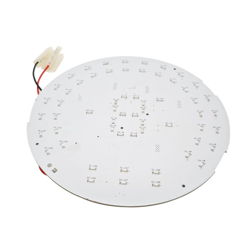
Ceiling Light PCBA Layout Example (Round)
A typical round ceiling light PCBA (150mm diameter, 36 LEDs) has this layer stack:
LayerFunctionCopper WeightTop (circuit layer)LED pads, traces, driver components2 ozDielectric layerElectrical isolation75-100 µmAluminum baseHeat spreading and mechanical support1.6mm thicknessBottom (optional)Secondary components or solder mask onlyN/A
Flicker and Dimming Considerations
Causes of Flicker
LED flicker occurs when the driver output current has significant ripple. Common causes:
- Insufficient output capacitance in the driver
- Poor TRIAC dimmer compatibility (leading edge dimmers with capacitive loads)
- Low-frequency PWM dimming (<1 kHz)
Flicker Metrics
MetricGoodAcceptablePoorPercent flicker (100Hz)<10%10-30%>30%Flicker index<0.10.1-0.3>0.3Flicker frequency>1 kHz100-1000 Hz<100 Hz
Flicker Reduction Techniques
TechniqueEffectCost ImpactAdd bulk output capacitor (100-470µF)Reduces 100-120 Hz rippleLow ($0.10-0.30)Increase PWM dimming frequency to >4 kHzEliminates visible flickerNone (firmware change)Use high-PF flyback or buck-boost topologyBetter voltage regulationModerate ($0.50-1.00)
Compliance and Certification
Required Certifications by Market
MarketCertificationRequirementUSAUL 1598 or UL 8750Safety for LED luminairesCanadaCSA C22.2 No. 250.0Safety for lighting fixturesEUCE (includes LVD, EMC, RoHS)Safety, emissions, hazardous substancesGlobalIEC 62031LED modules for general lightingEnergy efficiency (US)Energy Star or DLCRebate eligibility, utility requirements
Common Compliance Tests
TestStandardCriteriaDielectric strength (hipot)UL 87501500V AC for 1 minute, no breakdownGround continuityUL 8750<0.1Ω between ground terminal and exposed metalEMI (conducted & radiated)FCC Part 15 (US) or EN 55015 (EU)Below specified limitsPower factor and THDEnergy StarPF >0.90, THD <20% for commercial
Ceiling Light PCBA FAQs
Q1: Can I use the same ceiling light PCBA for both 120V and 277V commercial applications?
A: No, not without a universal input driver. Here is the technical breakdown:
A PCBA designed specifically for 120V AC uses components rated for approximately 200V DC bus voltage (after rectification). At 277V AC, the rectified DC bus is approximately 390V DC. This exceeds the voltage rating of standard 120V-rated capacitors, MOSFETs, and diodes.
Component voltage derating requirements:
Component120V Rating277V Required RatingInput capacitor200V400-450VMOSFET250-300V500-600VRectifier diodes200V400VCreepage distance1.5mm3.0mm
If you need a single PCBA for both voltages:
- Specify a universal input driver rated 90-277V AC
- Use components rated for 400V DC bus minimum
- Design PCB creepage for 3mm between AC lines and low-voltage sections
- Expect 10-20% higher component cost
Alternative: Create two PCBA variants---one for 120V (lower cost) and one for 277V (higher voltage rating). This is common in commercial lighting manufacturing.
Q2: How do I ensure my ceiling light PCBA works properly with a TRIAC wall dimmer?
A: TRIAC dimmer compatibility is a common challenge for ceiling light PCBA designers. Here is the engineering approach:
The problem: TRIAC dimmers were designed for incandescent bulbs (resistive loads). LEDs present a reactive load that can cause the TRIAC to misfire, leading to flicker, flashing, or failure to dim below 30%.
Solution 1 - Bleeder resistor (passive):
Add a bleeder resistor (10-50 kΩ, 1-2W) across the AC input. This draws enough current (5-15 mA) to keep the TRIAC conducting properly during each half-cycle.
Result: Improves low-end dimming (typically 10-15% minimum). Adds 1-2W of standby loss.
Solution 2 - Active bleeder circuit (preferred):
An active bleeder (IC-controlled) only draws current when the TRIAC would otherwise misfire. Efficiency loss is near zero.
Solution 3 - Specify TRIAC-dimming driver IC:
Many commercial LED driver ICs include built-in TRIAC dimming detection and bleeder control. Examples include:
- TI LM3447 (TRIAC dimmable LED driver)
- MPS MP4030 (TRIAC dimming primary-side regulator)
Testing requirement: Validate dimming compatibility with at least 5 different TRIAC dimmer models (Lutron, Leviton, Legrand). Dimmers vary significantly in their holding current requirements.
Field failure sign: If the ceiling light flickers or flashes when dimmed below 50%, the bleeder circuit is inadequate.
Q3: What are the most common quality issues in ceiling light PCBA manufacturing?
A: Based on thousands of production inspections, these five defects account for over 80% of ceiling light PCBA quality issues.
DefectFrequencyRoot CauseDetection MethodRework CostLED tombstoning1-5%Uneven solder paste volume on LED padsAOIHigh (LEDs damaged)Solder voids under LEDsCommonTrapped flux gases during reflowX-ray inspectionNone (voids <25% acceptable)Reverse polarity LEDs0.5-2%Feeder or placement errorVisual or AOI (color/marking)Very high (scrap board)Cold solder joints on driver IC1-3%Insufficient reflow temperatureAOI or manual inspectionMedium (rework possible)Insufficient thermal paste (MCPCB)5-10%Inconsistent applicationPull test or thermal imagingLow (add paste)
Prevention strategies:
LED tombstoning:
- Use stencil apertures that are slightly larger than the LED pads (1:1.1 ratio)
- Ensure reflow profile has 60-90 seconds time above liquidus (TAL)
Reverse polarity LEDs:
- Use LEDs with clear polarity marking (anode/cathode)
- Implement automated optical inspection (AOI) with polarity check
- Run 100% polarity test on flying probe or bed-of-nails
Cold solder joints:
- Verify reflow peak temperature (245-260°C for lead-free SAC305)
- Monitor oven profile daily with a profiler (not just once per batch)
Insufficient thermal paste (MCPCB to heatsink):
- Use stencil or screen printing for thermal paste (not manual application)
- Target 0.3-0.5mm paste thickness
- Verify coverage after mounting (thermal paste should squeeze out edges slightly)
Quality control checklist for incoming ceiling light PCBA inspection:
Inspection ItemMethodAcceptance CriteriaLED polarityVisual or AOI100% correctSolder joints (power components)AOINo bridging, no insufficient solderLED voidsX-ray (sample 5-10%)<25% per padThermal pasteVisual (edge squeeze-out)Visible at all mounting pointsElectrical testFlying probe or bed-of-nailsOpen/short, LED forward voltage check
Ceiling Light PCBA Manufacturing Checklist
Production StepRequirementVerificationPCB incoming inspectionNo warpage, correct thickness, ENIG finish visibleVisual and gauge measurementSolder paste printingStencil thickness 0.1-0.12mm, aperture alignment ±0.05mmSPI (solder paste inspection)Pick-and-placeLED placement ±0.05mm accuracyAOI after placementReflow solderingPeak 245-260°C, TAL 60-90 secondsProfiler data per batchThermal paste application0.3-0.5mm thickness, full coverageWeight check + visualHeatsink mountingUniform pressure, no gapScrew torque specificationElectrical testOpen/short, LED polarity, current measurementAutomated test fixture
Summary: Good Quality Ceiling Light PCBA Checklist
A good quality ceiling light PCBA balances cost, thermal performance, and compliance. For standard residential fixtures (15-25W), aluminum MCPCB with 2 oz copper, constant current driver, and LED pad temperatures under 60°C consistently achieves 50,000+ hour lifespan. For commercial dimmable fixtures, add TRIAC-compatible driver ICs and bleeder circuits. The most common manufacturing defects---LED tombstoning, reverse polarity, and cold joints---are preventable with AOI inspection and controlled reflow profiles.
| Design Element | Requirement |
|---|---|
| PCB material | Aluminum MCPCB for >15W; FR4 acceptable for <12W |
| Copper weight | 2 oz for power traces; 1 oz for signal |
| Thermal management | 9+ thermal vias per LED; LED pad temperature <60°C at full load |
| Driver topology | Constant current (integrated or remote) |
| Flicker control | Output capacitance 100-470µF; PWM dimming >4 kHz if used |
| Dimming compatibility | Bleeder circuit for TRIAC; dedicated dimming IC for best results |
| Voltage rating | Components rated for maximum input voltage (120V or 277V or universal) |
| Certifications | UL or CE based on target market; Energy Star for commercial |
| Manufacturing inspection | AOI (LED polarity, solder joints), X-ray (voids), electrical test |