- English
- Español
- Português
- русский
- Français
- 日本語
- Deutsch
- tiếng Việt
- Italiano
- Nederlands
- ภาษาไทย
- Polski
- 한국어
- Svenska
- magyar
- Malay
- বাংলা ভাষার
- Dansk
- Suomi
- हिन्दी
- Pilipino
- Türkçe
- Gaeilge
- العربية
- Indonesia
- Norsk
- تمل
- český
- ελληνικά
- український
- Javanese
- فارسی
- தமிழ்
- తెలుగు
- नेपाली
- Burmese
- български
- ລາວ
- Latine
- Қазақша
- Euskal
- Azərbaycan
- Slovenský jazyk
- Македонски
- Lietuvos
- Eesti Keel
- Română
- Slovenski
- मराठी
- Srpski језик

Avoiding Grounding Pitfalls and Screw Debris: Design Guidelines for High-Reliability Motor Control PCBAs
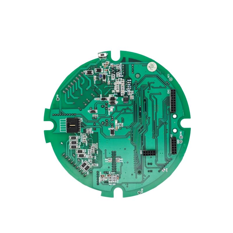
Motor Control PCBA (Printed Circuit Board Assembly) is the core enabler of precision motion control in industrial automation, robotics, new energy vehicles, and smart home appliances. This practical guide consolidates key insights from architecture selection, PCB layout, assembly, and verification, helping engineers and product managers avoid common pitfalls and ensure a smooth transition from prototype to high-volume manufacturing.
1. Design Phase: Architecture and Component Selection
1.1 Custom vs. Standard Solutions
At project initiation, assess whether to adopt a custom PCBA or an off-the-shelf standard module. While custom PCBA incurs higher upfront NRE (Non-Recurring Engineering) costs, it enables optimization for specific motor types—such as BLDC, stepper, or servo—and precise performance targets (e.g., speed/torque accuracy within ±0.5%). Custom solutions also offer superior system integration efficiency (often exceeding 95%) and long-term reliability under harsh operating conditions.
1.2 Core Chipset and Topology Selection
-
Processor: A 32-bit MCU with dedicated motor-control peripherals (e.g., ARM Cortex-M4 core) is strongly recommended to handle computationally intensive algorithms like Field-Oriented Control (FOC) with real-time response.
-
Driver and Power Stage:
-
For high-integration designs, choose fully integrated BLDC driver ICs (e.g., TI MCF831xC series) that combine gate drivers and power FETs. This simplifies external circuitry, but mandates careful decoupling—at least five critical capacitors (VM-PGND, CPH-CPL, etc.) must be placed per the datasheet to ensure stable operation.
-
For high-power applications (e.g., >50A), discrete MOSFETs/IGBTs with dedicated gate drivers are preferred. Consider wide-bandgap devices (SiC or GaN) to achieve higher switching frequencies and reduced losses.
2. PCB Layout: The Art of Noise Suppression and Thermal Management
A motor control board is inherently a mixed-signal and power-intensive assembly. Poor layout is the leading cause of EMC failures and field returns.
2.1 Circuit Partitioning and Grounding Strategy (Critical)
Golden Rule: Physically isolate power ground from signal ground.
-
Zoning: Divide the PCB into three distinct regions:
-
Noisy Zone: Power inverter, relays, and gate-drive loops.
-
Digital Zone: MCU, communication interfaces (CAN, UART, SPI).
-
Analog Zone: Current/voltage sensing, encoder/resolver inputs. Keep high-frequency PWM traces away from sensitive analog feedback paths.
-
Grounding Implementation:
-
Adopt a single-point grounding or split-ground-plane approach.
-
Connect digital and analog grounds at a single point near the ADC reference pin.
-
Isolate the power ground (noisy) and connect it to the system star-ground point via a low-impedance path, preventing large transient currents from corrupting control signals.
-
Stack-up Recommendation: A 4-layer board is ideal when budget permits. Use dedicated ground layers adjacent to the primary component side to provide low-inductance return paths and inherent shielding. For 2-layer designs, employ extensive ground flooding and keep power traces as short and wide as possible.
2.2 Power Loops and Thermal Dissipation
-
Trace Width and Loop Area: DC bus and three-phase output traces must be short and wide to withstand high di/dt. Gate-drive signal pairs should run parallel and close to the corresponding MOSFET source terminals to minimize parasitic inductance.
-
Thermal Management: Use thermal vias to efficiently conduct heat from power devices to inner copper planes or bottom-layer heatsink pads. Apply solder-mask openings (copper exposed) on high-current paths to enable auxiliary heatsink attachment.
3. Assembly and Manufacturing: Overlooked Yet Critical Details
3.1 Supply-Chain Resilience in BOM Planning
Before BOM (Bill of Materials) finalization, perform a supply risk assessment for long-lead items such as MCUs and communication transceivers. Where possible, reserve pin-compatible alternate footprints in the layout to avoid production halts caused by single-source supplier disruptions.
3.2 Screw Fastening Cleanliness (A Frequent but Ignored Failure Mode)
During motor controller PCBA assembly, metal debris carried by screws is a hidden killer that causes short circuits and insulation degradation.
-
Risk: Metal particles from vibrating screw feeders can fall onto high-density IC pins or between adjacent traces, leading to intermittent failures or immediate short circuits upon power-up.
-
Countermeasures:
-
Replace traditional vibratory bowl feeders with step-type feeders to minimize friction-induced particle generation.
-
Introduce a vacuum dust-removal station immediately before the fastening step.
-
Utilize smart electric screwdrivers with real-time torque and angle monitoring to prevent under-torquing (floating) or thread stripping.
4. Testing and Validation: Beyond "Does It Spin?"
-
Functional Test (FCT): Under loaded conditions, verify the response time of overcurrent and overtemperature protection—e.g., ensuring the driver shutdown is triggered within <10µs. Also validate dynamic power derating logic during voltage dips.
-
Electromagnetic Compatibility (EMC) Pre-Compliance: Conducted and radiated emissions (CE/RE) are common pain points. If failures occur, first check if a properly rated TVS diode and common-mode choke are placed at the power input, and optimize PWM switching slew rate by adjusting gate resistors.
-
Long-Term Reliability: Perform thermal cycling and continuous run tests to verify solder-joint integrity and component derating under maximum ambient temperatures.
Designing a reliable Motor Control PCBA is fundamentally a triangular trade-off among electrical performance, thermodynamics, and electromagnetic compatibility. Every decision—from clear circuit partitioning and disciplined grounding, to rigorous assembly cleanliness control—determines the product's long-term stability in challenging industrial environments. By implementing the strategies outlined in this guide, you can significantly reduce failure rates, shorten development cycles, and enhance the overall robustness of your motor control system.
Send Inquiry
-
Delivery Service



-
Payment Options