- English
- Español
- Português
- русский
- Français
- 日本語
- Deutsch
- tiếng Việt
- Italiano
- Nederlands
- ภาษาไทย
- Polski
- 한국어
- Svenska
- magyar
- Malay
- বাংলা ভাষার
- Dansk
- Suomi
- हिन्दी
- Pilipino
- Türkçe
- Gaeilge
- العربية
- Indonesia
- Norsk
- تمل
- český
- ελληνικά
- український
- Javanese
- فارسی
- தமிழ்
- తెలుగు
- नेपाली
- Burmese
- български
- ລາວ
- Latine
- Қазақша
- Euskal
- Azərbaycan
- Slovenský jazyk
- Македонски
- Lietuvos
- Eesti Keel
- Română
- Slovenski
- मराठी
- Srpski језик

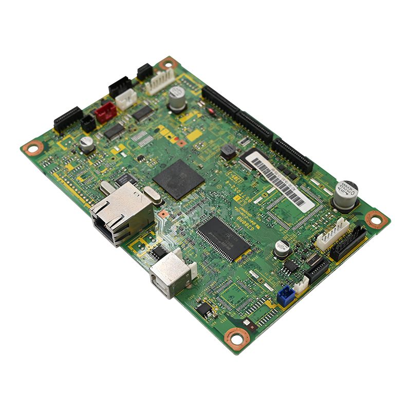
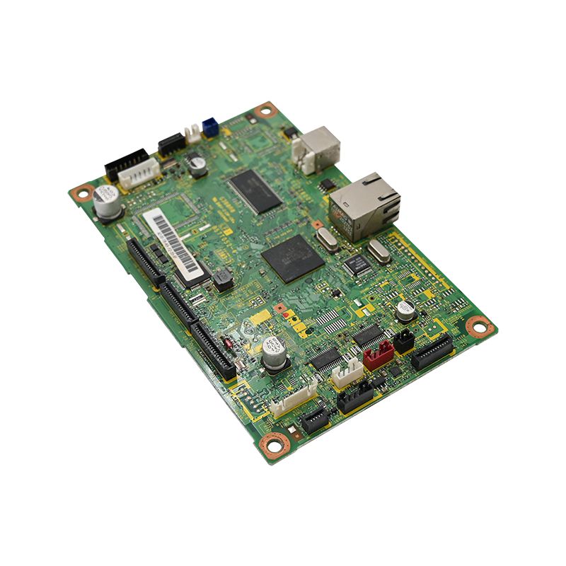
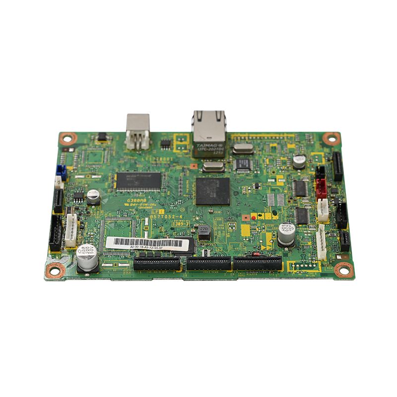
Radar Detector PCBA
Unixplore Electronics Co., Ltd. is a China Radar Detector PCBA Manufacturer and Supplier. With advanced SMT/DIP production capabilities, professional RF engineering experience, and strict quality control, our Radar Detector PCBA Factory supports automotive and security applications with reliable performance, fast delivery, and customized manufacturing services.
Send Inquiry
Product Description
Welcome to Unixplore Electronics Co., Ltd. Established in 2011, we are a premier one-stop turn-key Electronic Manufacturing Services (EMS) provider specializing in high-precision PCBA for the automotive and security sectors. With over 15 years of industry experience, an annual output of 1.5 million PCBAs, and a state-of-the-art 3,000 ㎡ industrial base, we deliver premium quality, faster delivery, and optimized costs for your radar detector projects.
Whether you are developing next-generation radar detectors for North American, European, or international markets, our expert engineering team and advanced SMT/DIP assembly lines ensure your RF and DSP designs are manufactured to the highest IPC-610E and ISO 9001:2015 standards.
Core Performance Parameters: Engineered for Precision
Before sourcing components, we ensure your baseline electrical and RF characteristics are perfectly defined and manufacturable.
Frequency Band Coverage
| Band | Frequency Range | Typical Use | PCBA Requirement |
|---|---|---|---|
| X | 10.50–10.55 GHz | Legacy radar | Low-noise amplifier (LNA) with <1.5 dB NF |
| K | 24.05–24.25 GHz | Moving radar | Stable VCO, harmonic filtering |
| Ka | 33.4–36.0 GHz | Photo radar | High-gain mixer, LO shielding |
| Ku | 13.4–13.5 GHz | International traffic | Wideband IF amplifier |
Sensitivity and Selectivity Metrics
Environmental and Power Specifications
| Parameter | Recommended Value | Reason |
|---|---|---|
| Operating voltage | 11–14 V DC (reverse protection built-in) | Automotive power variation |
| Current draw | <350 mA at 12 V | Avoid overheating in dash enclosures |
| Temperature range | -20°C to +85°C | Summer dash and winter cold starts |
| Vibration tolerance | 5 Grms, 10–500 Hz | Pothole and engine vibration |
Key Components Selection: Field-Proven Reliability
Every component impacts false alert rates and reaction time. We assist in sourcing and assembling field-proven choices:
Low-Noise Amplifier (LNA)
Mixer and Local Oscillator (LO)
IF Amplifier and Filter Chain
| Stage | Component | Spec | Purpose |
|---|---|---|---|
| 1st IF | Variable gain amp (VGA) | 20 dB range, 2.5 dB NF | Overload protection |
| Bandpass | SAW filter | Center 110 MHz, BW 40 MHz | K/Ka separation |
| 2nd IF | Limiting amp | 70 dB gain, RSSI output | Signal strength to ADC |
Critical Assembly Note: Our technicians place SAW filters after the VGA to prevent saturation from strong door opener signals.
Digital Processing Unit (DSP/MCU)
Power Management
Automotive radar PCBA demands robust power rails:
| Rail | Voltage | Current | Component |
|---|---|---|---|
| Analog (LNA, mixer) | 3.3 V | 150 mA | LDO with 50 µVrms noise |
| Digital (MCU, ADC) | 3.3 V | 200 mA | DC-DC + ferrite bead |
| LO/PLL | 5 V | 80 mA | LDO with PSRR > 70 dB at 1 kHz |
| Reverse protection | - | - | Schottky + TVS (24 V clamp) |
Unixplore Testing: We measure inrush current during functional testing to prevent fuse rating failures caused by bulk decoupling caps.
Advanced Layout and Shielding Capabilities
Premium components fail on a poor board. Our 20+ R&D engineers and advanced SMT lines ensure flawless execution:
Rigorous Testing and Validation
Backed by 2 aging test rooms, 2 high & low temperature test rooms, and state-of-the-art in-house testing instruments, we verify six critical points before shipping:
False alert rate: Urban environment simulation; ≤ 2 per hour (using recorded drive test)
Expert FAQ: Solving Common Radar PCBA Challenges
Q1: What is the most common failure mode and how do you prevent it?
A: LNA burnout from continuous high-power radar sources. We prevent this by integrating a fast-acting PIN diode limiter before the LNA (threshold at +3 dBm, reaction < 10 ns). We also embed temperature sensors on the LNA ground paddle, allowing the MCU to reduce gain or shut down the RF path if the die exceeds 85°C. Every production board passes a 1-watt continuous injection test at the antenna port for 2 minutes without permanent gain degradation.
Q2: How does PCBA component choice affect false alert filtering?
A: Three factors dominate:
- IF SAW filter bandwidth: A 40 MHz bandwidth passes valid radar pulses and rejects 5G cellular interference.
- ADC resolution: 12 bits allows 60 dB dynamic range; 10 bits loses weak signals near the noise floor.
- Clock reference accuracy: A ±25 ppm TCXO ensures FFT bins align with actual radar frequencies. We assemble dual-core MCUs to run real-time FFT and pattern recognition simultaneously.
Q3: Can the same PCBA design be reused for different regional radar bands (EU vs USA)?
A: Yes. We implement three mandatory changes:
- Input filter: Switchable band-pass filter network (PIN diode/MEMS) for K/Ka (USA) or Ku/K (EU).
- LO frequency plan: Programmed PLL synthesizer covering 10.5 GHz, 13.4 GHz, or 24.15 GHz with an octave tuning VCO core.
- Calibration constants: Per-band LNA bias and mixer conversion loss stored in EEPROM, read via DIP switch or GPS geofencing at boot.
Why Choose Unixplore Electronics for Your Radar Detector PCBA?
Ready to Start Your Project?
Choosing components for a radar detector PCBA is about matching noise figure, intercept points, and thermal drift to real driving environments. Start with your frequency plan, and let Unixplore build around your LNA and IF filter chain.
Send us your Gerber files and BOM list today, and receive a customized quotation within 24 hours!
[Contact Us Now / Request a Quote]
Hot Tags: Radar Detector PCBA, China, Manufacturers, Suppliers, Factory, Customized, Cheap, Quality, Advanced, CE, 1 Year Warranty, Price
Related Category
Home Appliance PCBA
Industrial Control PCBA
Automobile PCBA
Consumer Electronics PCBA
Medical Equipment PCBA
Security System PCBA
Healthcare PCBA
LED Lighting PCBA
IoT PCBA
Electric Gardening Tool PCBA
Send Inquiry
Please Feel free to give your inquiry in the form below. We will reply you in 24 hours.