- English
- Español
- Português
- русский
- Français
- 日本語
- Deutsch
- tiếng Việt
- Italiano
- Nederlands
- ภาษาไทย
- Polski
- 한국어
- Svenska
- magyar
- Malay
- বাংলা ভাষার
- Dansk
- Suomi
- हिन्दी
- Pilipino
- Türkçe
- Gaeilge
- العربية
- Indonesia
- Norsk
- تمل
- český
- ελληνικά
- український
- Javanese
- فارسی
- தமிழ்
- తెలుగు
- नेपाली
- Burmese
- български
- ລາວ
- Latine
- Қазақша
- Euskal
- Azərbaycan
- Slovenský jazyk
- Македонски
- Lietuvos
- Eesti Keel
- Română
- Slovenski
- मराठी
- Srpski језик

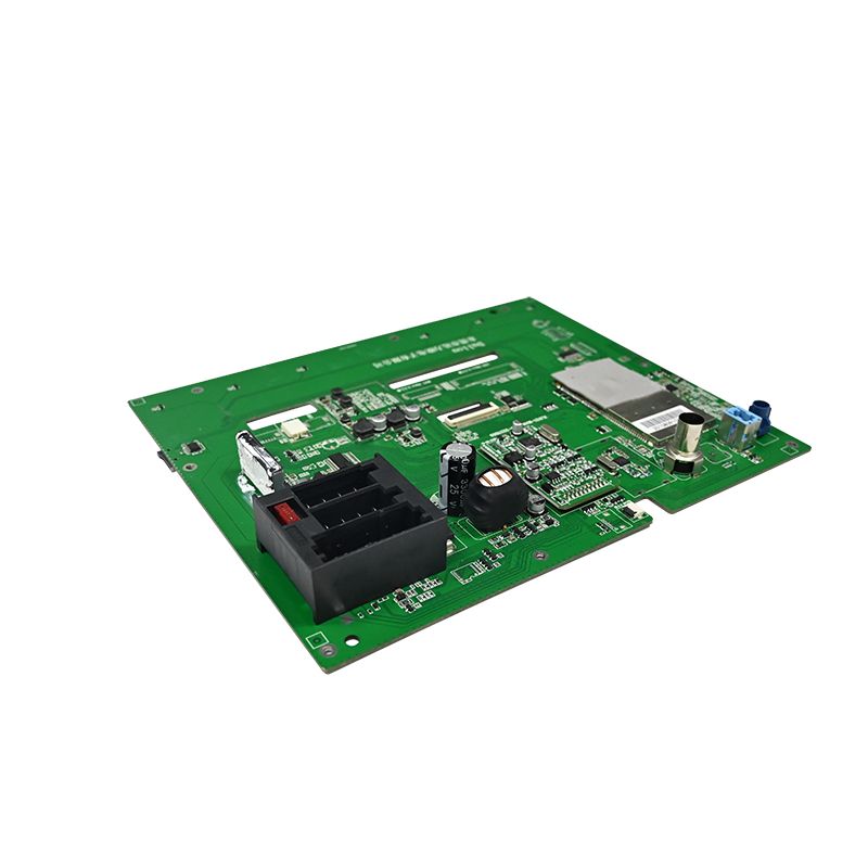
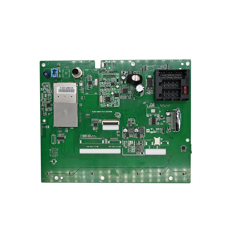
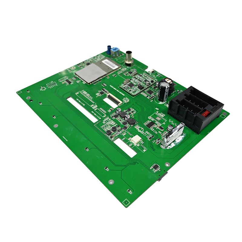
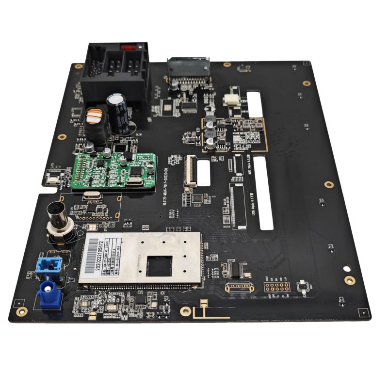
Dash Cam PCBA
Unixplore Electronics Dash Cam PCBA is a reliable automotive camera PCB solution developed by a professional Dash Cam PCBA Manufacturer and Supplier in China. Designed for vehicle monitoring applications, this PCBA supports automotive-grade component selection, thermal management, vibration resistance, and strict manufacturing controls to ensure stable recording performance in harsh environments.
Send Inquiry
Product Description
Core Quality Specifications for Dash Cam PCBA
Define these parameters before component sourcing. Every decision flows from thermal and vibration requirements.
Operating Environment for Automotive Use
| Parameter | Required Spec | Real-World Condition |
| Temperature range | -30°C to +85°C (ambient) | Windshield solar load |
| Peak internal temp | +105°C (processor junction) | Black housing in Arizona summer |
| Vibration | 10 Grms, 10–1000 Hz | Potholes and rough roads |
| Input voltage | 9–16 V DC (24 V truck optional) | Alternator load dump |
| Recording uptime | 99.9% over 1 year | No missed clips |
Thermal Management Budget
| Component | Max Junction Temp | Cooling Method |
| Image sensor | 70°C | Thermal pad to shield can |
| Processor (H.264 encoder) | 85°C | Exposed pad + 12 vias |
| DRAM | 85°C | Keep 5 mm from hot spots |
| Power MOSFETs | 105°C | Copper pour (2 oz) |
Critical: Derate all electrolytic capacitors to 50% voltage rating at 105°C. A 6.3V cap on 5V rail fails within 6 months.
Component Selection for High-Quality Dash Cam PCBA
Good quality starts with automotive-grade parts. Consumer-grade components cause field failures.
Image Sensor and Lens Assembly
| Parameter | Minimum Spec | Why It Matters |
| Sensor type | CMOS, back-illuminated (BSI) | Low-light plate capture |
| Resolution | 1920×1080p @ 60 fps | Readable license plates |
| Pixel size | 2.0 µm or larger | Signal-to-noise ratio |
| Dynamic range | > 110 dB | Tunnel exits and night glare |
| Lens mount | M12 with locking ring | Vibration-proof focus |
Avoid rolling shutter sensors without global reset. Fast motion produces skew that makes plates unreadable.
Processor and Memory Architecture
| Component | Recommended Part | Critical Spec |
| SoC | Novatek NT96670 or Ambarella A12 | H.265 encoder, 2-ch input |
| DRAM | DDR3L (1.35V) | 1 GB minimum, -40°C rated |
| Flash | SPI NOR (32 MB) | Bootloader + calibration data |
| Storage | SD card controller (UHS-I) | CRC error checking |
Reliability rule: Use a separate LDO for the DDR memory reference voltage (VREF). Tying it to VDD via resistor divider causes bit flips above 70°C.
Power Supply Chain (Most Critical)
A dash cam PCBA fails here more than anywhere else.
| Rail | Voltage | Current | Protection Required |
| Input | 12V nominal | 1A max | TVS (24V clamp), reverse polarity |
| Core | 1.1V | 800 mA | Soft-start, overcurrent at 1.2A |
| I/O | 3.3V | 300 mA | Sequencing: 3.3V before 1.1V |
| Sensor | 2.8V (analog) | 150 mA | 10 µVrms noise max |
| Motor (lens autofocus) | 5V | 200 mA | Separate switch, inrush limiting |
Inject 200 mVpp ripple at 100 kHz on 12V input. Video should show no horizontal bars.
PCBA Layout for Signal Integrity and Heat Spreading
Layout determines if a dash cam PCBA records reliably or locks up in traffic.
Layer Stack Recommendation (6-Layer Minimum)
| Layer | Function | Constraint |
| 1 | Components, image sensor | Keep DDR traces matched length (±2 mm) |
| 2 | Ground | Continuous under SoC and DRAM |
| 3 | DDR signals, SDIO | Reference to ground plane |
| 4 | Power (1.1V, 3.3V) | Split with 30 mil gaps |
| 5 | Ground (aux) | Stitch to layer 2 via every 3 mm |
| 6 | Secondary components, USB | No traces under crystal |
Critical Routing Rules
DDR3L traces – 50Ω ±10% impedance, group 8 traces within 0.5 mm length
MIPI CSI (sensor to SoC) – differential pairs, length mismatch < 0.2 mm
SD card slot – series 22Ω resistors near SoC for overshoot control
Crystal (27 MHz) – guard ring with grounded vias, no power plane underneath
Manufacturing Process Controls for Consistency
High-quality dash cam PCBA requires statistical process control (SPC) on every line.
Solder Paste and Reflow
| Process Step | Specification | Inspection Method |
| Stencil thickness | 0.10 mm (laser-cut) | 2D SPI (volume tolerance ±20%) |
| Reflow peak (lead-free) | 245°C ±3°C | Profiler (5 zones min) |
| Time above liquidus | 60–90 seconds | K-type thermocouple on DRAM |
| Nitrogen purge | 1000 ppm O2 max | Reduces voiding under SoC |
Optical and X-Ray Inspection
AOI (automated optical) – checks component polarity, solder bridges, lifted leads
AXI (X-ray) – mandatory for BGA packages (SoC and DRAM). Void ratio under ball < 25%
ICT (in-circuit test) – verifies power rails, clocks, and reset signals before firmware flash
Validation Tests Before Mass Production
Every dash cam PCBA design must pass these six tests.
| Test | Method | Pass/Fail Criteria |
| Thermal cycling | -30°C to +85°C, 100 cycles | No video freeze, RTC drift < 2 ppm |
| Drop shock | 1m onto concrete, 3 orientations | No SD card ejection, no reboots |
| Overvoltage | 24V for 60 seconds | TVS clamps, PCBA resumes after power cycle |
| ESD contact | ±8 kV on USB connector | No frame loss, no reset |
| RF immunity | 20 V/m, 80–2700 MHz | No flicker on display |
| Accelerated life | 85°C / 85% RH for 500 hours | No corrosion on micro-USB port |
FAQ – Common Questions About Dash Cam PCBA Quality
Q1: Why do many dash cam PCBA designs fail after 6 months of parking mode?
A: The primary failure is supercapacitor or battery degradation from continuous top-off charging in high heat. Parking mode keeps the dash cam PCBA active for 12+ hours daily at 60–80°C windshield temperatures. Three specific failures occur:
1.Supercapacitor ESR rise – Standard 2.7V/10F caps increase equivalent series resistance from 50 mΩ to over 1Ω after 2000 hours at 70°C. This prevents the final file flush when ignition cuts off. Use automotive supercaps rated at 85°C with initial ESR < 30 mΩ.
2.LDO thermal shutdown – The 3.3V LDO powers motion detection while parked. Without a dedicated buck converter (90% efficient vs 60% for LDO), junction temperature exceeds 125°C. Switch to a synchronous buck with spread spectrum.
3.RTC battery leakage – Coin cell backup batteries (CR1220) leak electrolyte above 80°C, corroding nearby traces. Replace with a 0.1F supercapacitor for RTC backup – no leakage risk.
Always verify parking mode with thermal camera after 4 hours in a 50°C oven.
Q2: How does PCBA component placement affect night video quality in dash cams?
A: Component placement impacts electrical noise coupling into the image sensor's analog power and clock lines. Three placement rules directly affect night footage:
Keep switching regulators 30 mm away from sensor – The 2 MHz ripple from a DC-DC converter couples into the sensor's 2.8V analog rail if traces run parallel. Measure with a spectrum analyzer – any spur above -85 dBV at the pixel clock frequency creates vertical banding in low light.
Separate digital I/O from MIPI lanes – SD card data lines (up to 200 MHz harmonics) radiate into the differential MIPI clock when routed on adjacent layers. Add a grounded via fence between SDIO and MIPI regions.
Place decoupling caps within 1 mm of sensor – A 4.7 µF ceramic cap at each power pin absorbs high-frequency noise. Caps farther than 2 mm increase noise by 15 dB, visible as horizontal stripes in shadows.
A well-laid dash cam PCBA produces clean night video where license plates are readable at 5 lux. Poor layout adds artifacts that fail forensic review.
Q3: Can I use the same dash cam PCBA for front and rear cameras?
A: No, due to three hardware differences that cannot be resolved by firmware alone:
Lens focus distance – Front cameras require infinity focus (3 meters to horizon). Rear cameras need close focus (0.5 meters to bumper) for hatchback interiors. The lens barrel height differs by 1.2 mm. A common PCBA with adjustable lens holder costs more than two dedicated designs.
Image sensor orientation – Front cameras are mounted upright. Rear cameras often mount upside-down (headliner to glass). The sensor reads pixels from top to bottom. Flipping the image digitally adds a 1-frame latency (33 ms at 30 fps), causing sync mismatches in dual-channel recordings. Hardware flip via register setting requires different sensor configuration files.
Thermal environment – Rear windshield receives 30% less solar load than front. A front-optimized PCBA with aggressive power throttling may never engage cooling on the rear, leading to capacitor aging mismatch. Two years of operation will show front unit failing before rear.
Instead, design a common motherboard with two mezzanine sensor boards. The base dash cam PCBA holds processor and power. Each sensor board has its own lens mount, orientation pins, and thermal pad thickness. This approach reduces total SKUs while preserving image quality.
Production Yield Targets for Good Quality
| Process Stage | Acceptable Yield | Action if Below |
| Bare board test (flying probe) | > 99.5% | Audit via placement |
| SMT placement | > 99.8% | Check feeder calibration |
| ICT + firmware | > 98.5% | Review test fixture pogo pins |
| Final video test (30 min run) | > 99% | Burn-in 5% sample |
A good quality dash cam PCBA survives three years of daily temperature swings, vibration, and voltage transients. Design with automotive derating, validate with thermal imaging, and audit every production lot. This approach delivers dash cams that capture the moment that matters.
Hot Tags: Dash Cam PCBA, China, Manufacturers, Suppliers, Factory, Customized, Cheap, Quality, Advanced, CE, 1 Year Warranty, Price
Related Category
Home Appliance PCBA
Industrial Control PCBA
Automobile PCBA
Consumer Electronics PCBA
Medical Equipment PCBA
Security System PCBA
Healthcare PCBA
LED Lighting PCBA
IoT PCBA
Electric Gardening Tool PCBA
Send Inquiry
Please Feel free to give your inquiry in the form below. We will reply you in 24 hours.