- English
- Español
- Português
- русский
- Français
- 日本語
- Deutsch
- tiếng Việt
- Italiano
- Nederlands
- ภาษาไทย
- Polski
- 한국어
- Svenska
- magyar
- Malay
- বাংলা ভাষার
- Dansk
- Suomi
- हिन्दी
- Pilipino
- Türkçe
- Gaeilge
- العربية
- Indonesia
- Norsk
- تمل
- český
- ελληνικά
- український
- Javanese
- فارسی
- தமிழ்
- తెలుగు
- नेपाली
- Burmese
- български
- ລາວ
- Latine
- Қазақша
- Euskal
- Azərbaycan
- Slovenský jazyk
- Македонски
- Lietuvos
- Eesti Keel
- Română
- Slovenski
- मराठी
- Srpski језик

Why Is Aging Testing Important for LED Lighting Electronic Assemblies?
Why Is Aging Testing Important for LED Lighting Electronic Assemblies?
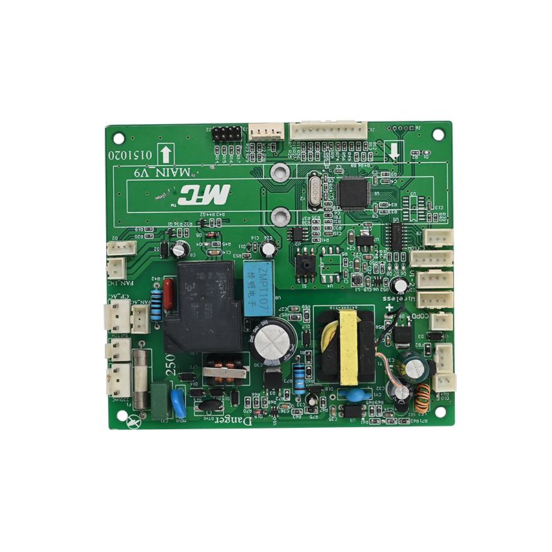
Aging testing is an important production quality control step for LED Lighting PCBA because it allows an assembled circuit to operate under defined conditions before it is released for delivery. During this period, engineers can observe whether the board starts correctly, maintains stable electrical output, controls the light source as intended and shows signs of abnormal heating or intermittent operation. The purpose of our aging process is not to make a new board artificially old. It is to expose certain early-life weaknesses that may not appear during a short power-on check, such as marginal solder joints, component defects, assembly contamination or unstable power circuitry.
For lighting manufacturers, a field failure can mean more than replacing one circuit board. A failed driver or control board may require access to a ceiling fixture, streetlight, sign, industrial luminaire or other installed product. Labour, access equipment, transport and customer disruption can make a small electronic defect expensive to resolve. A controlled burn-in stage can therefore add value when it is matched to the design and application. Unixplore Electronics Co., Ltd. provides turnkey electronic manufacturing services in Dongguan, including PCB design and fabrication, component procurement, SMT and DIP assembly, programming, functional testing and finished-product assembly. Its published factory information also identifies two aging test rooms and two high- and low-temperature and humidity test rooms.
Contents
1. What Early Failures Can Aging Testing Reveal?
2. How Should an LED PCBA Aging Test Be Planned and Performed?
3. What Manufacturing and Inspection Controls Make Aging Results Useful?
What Early Failures Can Aging Testing Reveal?
The first reason to include aging in an electronic assembly quality plan is that some defects are time-dependent. A quick functional test confirms that a board can power up and perform selected operations at one moment. It does not necessarily show whether the same board will remain stable after components warm up, solder connections experience thermal expansion or the power supply reaches its normal operating temperature. Aging testing keeps the assembly running for a specified period while selected electrical and thermal behaviours are monitored. This creates an opportunity to identify early failures before the board enters a finished luminaire or is shipped to an end customer.
LED lighting circuits commonly combine power conversion, current regulation, switching devices, control ICs, capacitors, resistors, inductors, connectors and LED load interfaces. The exact circuit varies by product. In an LED Lighting PCBA, a constant-current driver, for example, must regulate current within its design limits as input conditions and load characteristics change. A control board may also handle dimming signals, sensors or communication functions. During continuous operation, a weak component or marginal connection can become more apparent as the board reaches thermal equilibrium. The objective is to assess the actual design under an approved test profile, not to apply an arbitrary high temperature or excessive input voltage.
Several defect categories are particularly relevant:
- Intermittent solder connections: A joint with insufficient wetting, a crack or poor mechanical support may behave normally during a brief test but become unstable as the board heats and cools. Symptoms can include flickering, resets, momentary loss of output or a complete open circuit.
- Component instability: A marginal capacitor, semiconductor, resistor or magnetic component may drift outside its expected operating behaviour after warming. Monitoring the relevant voltage, current, ripple or control signal can help reveal the problem.
- Power-stage abnormalities: Switching devices, rectifiers, transformers and inductors can generate abnormal heat or noise if component selection, soldering, layout or operating conditions are incorrect.
- Connector and wiring faults: Poor contact, incorrect polarity, loose terminals or inadequate crimping can cause voltage drop, local heating or intermittent operation under load.
- Assembly contamination or handling damage: Residues, conductive debris, damaged components and handling-related defects may contribute to leakage paths or unexpected behaviour, depending on board design and cleanliness requirements.
- Control and programming issues: Firmware, configuration or dimming behaviour may appear correct during a basic start-up but fail during extended operation or repeated command sequences.
Thermal behaviour deserves particular attention because LED drivers are power electronic systems. Heat is produced by switching losses, conduction losses and the operation of other components. If the PCB layout, copper distribution, enclosure or heat-transfer path is inadequate, component temperatures may rise beyond the intended design condition. Electrolytic capacitors are a known life-limiting component in many driver designs, and elevated operating temperature can accelerate electrolyte degradation. Research discussed by the Illuminating Engineering Society notes that driver life can limit the useful life of an LED lighting system even when the LED package itself is expected to last much longer. A burn-in check cannot establish the full service life of a capacitor, but it can reveal abnormal heating or early instability that warrants investigation.
Aging should also be distinguished from accelerated life testing. Production burn-in generally looks for early failures by operating assembled units under a defined condition for a limited period. Accelerated testing deliberately applies controlled stress, such as elevated temperature, humidity, electrical loading or cycling, to study degradation mechanisms or compare design robustness. The stress level must be selected carefully: an excessive condition can create a failure mode that would not occur in normal service, while a mild condition may not reveal the weakness being investigated. The US Department of Energy's guidance on LED luminaire lifetime explains that accelerated tests should use stress factors relevant to the product and that burn-in is one part of a broader reliability strategy.
For a buyer, the practical value of aging is therefore not the phrase "burn-in tested" on a quotation. It is knowing what was operated, under which electrical and environmental conditions, for how long, and against which pass criteria. If a supplier cannot explain these points, the test may be little more than an undocumented power-on period. Unixplore Electronics Co., Ltd. lists aging rooms as part of its in-house production resources, which provides a basis for discussing a project-specific aging plan. The actual protocol should still be confirmed against the board design, load, enclosure and customer specification by Unixplore Electronics Co., Ltd.
How Should an LED PCBA Aging Test Be Planned and Performed?
A useful LED Lighting PCBA aging procedure begins before a board enters the test room. The engineering team should identify the product's normal operating range, intended load, input supply, cooling arrangement, control functions and foreseeable installation environment. These details determine whether the board should be tested as a bare assembly, connected to a representative LED load or installed in a partial or complete luminaire. Testing a board without its normal thermal interface can produce a different temperature profile from testing it inside the final housing. Likewise, operating a driver at no load may not reveal behaviour that only appears at its rated output condition.
Our test specification should be written so that production operators can repeat it and quality staff can verify it. A practical plan normally defines the following items:
- Test sample and traceability: Identify the product revision, work order, production batch, component lot where relevant and sample quantity. For a 100 percent production burn-in, define how each unit is identified and how failed units are segregated.
- Input conditions: State the permitted input voltage, frequency where applicable, polarity and supply stability. The values must come from the approved electrical specification rather than a generic LED industry assumption.
- Output load: Specify the LED module or electronic load, target current or voltage, operating mode and any dimming or control state required during the test.
- Environmental condition: Define ambient temperature, airflow, humidity if controlled, fixture orientation and spacing. Avoid placing boards so close together that one unit changes the temperature of another.
- Duration and cycling: Set the operating period and decide whether the design requires continuous operation, repeated start-stop cycles or transitions between operating modes.
- Monitoring and acceptance: Identify the electrical readings, visual observations, temperature points, functional checks and failure criteria that determine pass or fail.
- Records and disposition: Record start and finish times, equipment identification, operator, measured results, alarms, failures, rework and retest status.
During the run, our test plan should monitor behaviours that relate directly to the design. Depending on the circuit, these may include input voltage and current, output current, output voltage, power, power factor, current ripple, dimming response, status indicators and abnormal sound. Temperature measurements may be taken at selected components, heat-spreading areas or designated test points. Infrared imaging can help locate unexpected hot spots, while thermocouples provide readings at defined positions. The measurement method matters: a temperature value without a stated measurement location, sensor attachment method and ambient condition is difficult to compare between batches.
Visual observation remains useful in our quality process even when automated equipment is available. Operators should look for flicker, unexpected shutdown, repeated restarting, unusual noise, smoke, odour, discolouration or visible component damage. Any abnormal event should trigger a controlled stop and a documented investigation rather than an informal reset. If a unit fails, the board should be quarantined and linked to its production and test records. Replacing a component and immediately passing the unit through the same test without recording the repair can hide a recurring process issue.
Test conditions must not be confused with universal product ratings. For example, an 85 degrees Celsius and 85 percent relative humidity test is used in some component and reliability studies, but it is not a default production burn-in condition for every lighting assembly. A research paper on solid-state lighting drivers used 85 degrees Celsius and 85 percent relative humidity without electrical bias to investigate moisture-related effects in a specific study. That research condition should not be copied into a production procedure unless the product design, component ratings and test objective justify it. The same principle applies to elevated input voltage and overcurrent: stress should be engineered, not guessed.
It is also important to separate board-level aging from luminaire-level verification. A board-level test can confirm electrical operation and selected thermal behaviour of an LED Lighting PCBA. A complete luminaire may additionally require checks of light output, colour characteristics, optical performance, enclosure temperature, ingress protection, electrical safety and electromagnetic compatibility, depending on the product and market. Long-term LED package lumen maintenance testing is a different activity again. IES LM-80, for example, concerns measurement of lumen maintenance of LED packages, arrays and modules under specified conditions; a short production burn-in is not a substitute for that type of long-duration measurement.
Unixplore Electronics Co., Ltd. describes a turnkey manufacturing route that includes PCB fabrication, procurement, SMT and DIP assembly, programming, functional testing, cable and wire-harness work, finished-product assembly and packaging. This integrated route can make it easier to connect aging results with upstream manufacturing records, provided the project defines the required data and reporting format. Our factory has two aging test rooms and two high- and low-temperature and humidity test rooms according to the published facility information. Buyers should confirm the available chamber capacity, temperature uniformity, loading arrangement, monitoring method and test duration for their specific order before treating those facilities as evidence of a particular test capability.
What Manufacturing and Inspection Controls Make Aging Results Useful?
Aging testing is most effective when it is one checkpoint in a controlled manufacturing process. It cannot compensate for poor component selection, incorrect PCB design, weak soldering control or incomplete functional verification. The board must first be built to our approved bill of materials and manufacturing data. If the wrong capacitor, resistor value, LED connector or switching device is installed, a burn-in test may not reveal the underlying mismatch during a short run. Process control before aging is therefore just as important as the test itself.
For an LED Lighting PCBA, the manufacturing route usually combines several operations with different quality risks. PCB fabrication determines the board construction and copper features. Component procurement introduces risks related to authenticity, storage condition and specification changes. SMT assembly controls component placement and reflow soldering. DIP or through-hole assembly adds insertion, solder fill and lead-trimming considerations. Programming and functional testing confirm that the board performs its intended control functions. Cable assembly and final product integration introduce connector polarity, wire routing, strain relief and mechanical fit concerns. A defect at any of these stages can affect the outcome of aging.
The following controls are worth discussing with a contract manufacturer before production begins:
- Approved engineering data: Confirm the PCB files, bill of materials, assembly drawing, firmware revision, test points and product specification are aligned. A revision mismatch can make a technically correct test irrelevant to the delivered product.
- Incoming component control: Define supplier approval, part-number verification, lot traceability and handling requirements for moisture-sensitive devices where applicable.
- SMT process inspection: Use suitable solder-paste inspection, placement verification and automated optical inspection where specified by the process and product risk.
- Through-hole workmanship: Inspect solder joints, polarity, lead condition and mechanical support on DIP components and connectors.
- Electrical functional test: Verify the key operating functions before aging so that the aging period is not used as a substitute for basic test coverage.
- Thermal design review: Check component derating, copper area, thermal vias where applicable, heat-sink contact and enclosure airflow against the intended load.
- Failure analysis: Record symptoms, identify the root cause, implement corrective action and verify the effectiveness of the change on subsequent production.
For LED driver assemblies, the most meaningful monitored values depend on the topology. A constant-current design may require output-current stability and ripple checks. A constant-voltage design may need output-voltage regulation and load-response checks. A dimmable circuit should be evaluated at the specified dimming levels and control interface. If the product includes a microcontroller, sensor or wireless function, the test script may need to exercise startup, communication, state retention and recovery after a power interruption. The test plan should be based on the product's functional specification, not on a generic checklist applied identically to every board.
Unixplore's published company information states that its manufacturing site in Dongguan covers more than 3,000 square metres and has 20 R&D engineers, six SMT production lines, four DIP assembly lines and two finished-product assembly lines. The same information lists two aging test rooms and two high- and low-temperature and humidity test rooms. It also identifies ISO 9001:2015, UL and an IPC-610E assembly standard, with RoHS-compliant manufacturing processes. Buyers should confirm the scope of each certificate, the applicable product or facility, the current revision of the workmanship standard and whether a requested compliance document applies to the exact assembly being quoted.
For clarity, the available company information supports the manufacturing resources and service scope shown below. It does not publish a universal electrical rating, board size or fixed aging recipe for every lighting board. Those values need to be defined by the customer's design files and product requirements.
| Manufacturing or quality item | Published information | What the buyer should confirm |
| Factory area | More than 3,000 square metres | Production location and capacity allocation for the project |
| Engineering team | 20 R&D engineers | Engineering support scope, design review and change control |
| SMT production | 6 SMT production lines | Inspection coverage, process capability and line allocation |
| DIP assembly | 4 DIP assembly lines | Through-hole soldering method and workmanship criteria |
| Finished-product assembly | 2 assembly lines | Integration, wiring, enclosure and packaging requirements |
| Aging facilities | 2 aging test rooms | Test duration, loading capacity, monitoring and pass criteria |
| Environmental test rooms | 2 high- and low-temperature and humidity test rooms | Available temperature and humidity range and test profile |
| Quality credentials stated | ISO 9001:2015, UL, IPC-610E and RoHS-compliant processes | Certificate scope, validity and product-specific applicability |
| Technical parameter | Information currently published | Project detail to confirm |
| PCB thermal construction | Unixplore's product listing identifies aluminum-backed PCB options for LED lighting applications | Substrate type, dielectric layer, board thickness and thermal requirements |
| Copper thickness | High-current traces up to 3 oz copper are stated in the company's LED product listing | Actual copper weight, trace width, current and temperature-rise design |
| Input and output ratings | Not specified as a universal rating | Input voltage, frequency, output voltage, current and rated power |
| Driver configuration | Depends on the customer design | Constant-current or constant-voltage topology, dimming method and control interface |
| Operating environment | Not specified as a universal rating | Operating temperature, humidity, enclosure conditions and application category |
| Aging profile | Two aging test rooms are listed in the factory information | Duration, load, ambient condition, sample quantity and acceptance criteria |
When comparing suppliers, request a sample aging report rather than relying only on a statement that our aging service is available. A useful report should identify the product revision, sample quantity, test setup, applied input, load condition, ambient condition, duration, monitored parameters, acceptance criteria and any failures. If the supplier performs 100 percent aging, ask how units are identified, how failed boards are segregated and whether retest results remain traceable. If only sampling is used, the sampling plan and its relationship to product risk should be clear.
Unixplore Electronics Co., Ltd. can be evaluated as a turnkey manufacturing partner by reviewing how its design, sourcing, assembly, programming, functional test and aging resources are connected within the agreed quality plan. Our factory's listed equipment and production lines provide useful context, but the decisive evidence for a particular project is the approved process flow, test specification, inspection records and corrective-action method. A reliable supplier should be able to explain not only what our process tests, but why each test is relevant to the intended lighting application.
Conclusion
Aging testing matters because it gives LED lighting manufacturers an opportunity to identify selected early-life defects under controlled operating conditions before assemblies are integrated into finished products or delivered to customers. The value of our approach depends on a test profile that reflects the circuit design, rated load, thermal arrangement and intended use. It should complement, not replace, functional testing, process inspection, electrical safety assessment, environmental qualification and long-term reliability evaluation.
Unixplore Electronics Co., Ltd. offers turnkey electronic manufacturing in Dongguan, with PCB design and fabrication, component procurement, SMT and DIP assembly, programming, functional testing, finished-product assembly and in-house aging and environmental test rooms listed among its resources. If you are developing a new lighting product or reviewing an existing supply chain, share your board files, bill of materials, operating requirements and inspection expectations with our engineering team. We can review the manufacturing route and discuss a project-specific LED Lighting PCBA production and aging plan based on your actual requirements.
Frequently Asked Questions
How long should an LED lighting PCBA remain in an aging test?
There is no single duration that suits every LED lighting assembly. The appropriate period depends on the circuit topology, component ratings, operating load, thermal design, application risk and customer acceptance criteria. A short production burn-in may be used to screen for early failures, while a longer engineering test may be needed to investigate a specific weakness. The supplier should document the selected duration and explain why it is suitable for the product rather than presenting one fixed number as an industry-wide requirement.
Does passing an aging test prove that an LED driver will last for its rated service life?
No. Passing a production aging test shows that the tested assembly operated within the defined acceptance criteria during that test period. It does not prove a specific number of operating hours in the field. Useful-life assessment also depends on component reliability data, operating temperature, electrical stress, thermal design, environmental exposure, duty cycle and long-duration testing or modelling. Buyers should treat burn-in as an early-failure screening measure within a wider reliability programme.
What parameters should be monitored during LED PCBA burn-in?
The monitored parameters should follow the board's electrical specification. Depending on the design, they may include input voltage and current, output voltage or current, power, current ripple, dimming response, functional status and temperature at selected components or test points. The report should state measurement locations, instruments, test conditions and our agreed acceptance limits. Monitoring only whether a board remains switched on may miss drift, abnormal heating or unstable output.
Is aging testing the same as high-temperature and humidity testing?
No. Aging or burn-in generally operates an assembly for a defined period to identify early failures and observe functional stability. High-temperature and humidity testing exposes a product to a controlled environmental condition to assess moisture-related or temperature-related weaknesses. The two methods can be complementary, but their objectives, stress profiles and acceptance criteria are different. A project may require one or both depending on the installation environment and product risk.
What should buyers request from a PCBA manufacturer before approving an aging process?
Buyers should request a written test specification covering the board revision, sample quantity, input conditions, output load, ambient temperature, test duration, monitored parameters, pass criteria, failure handling and report format. They should also confirm how failed units are quarantined, repaired, retested and traced to the production batch. This information makes it possible to compare suppliers on actual process control rather than on an unsupported claim that every board is aged.
Send Inquiry
-
Delivery Service



-
Payment Options