Abstract
Thermal stability in a temperature controller is rarely decided by the control algorithm alone. It is shaped by a chain of manufacturing decisions: how the sensor front end is isolated from power copper, how solder joints survive repeated thermal excursions, how contamination is removed before conformal protection, and how every unit is screened before it enters the field. This article examines the manufacturing variables that separate a stable controller from one that drifts, oscillates, or fails prematurely. It discusses sensor-interface layout, material selection, reflow uniformity, test coverage, coating strategy, and traceability, with reference to the capabilities required for a reliable Temperature controller PCBA in automotive, medical, and industrial environments.
- 1. Why Thermal Stability Is a Manufacturing Outcome
- 2. Sensor Interface: The First Line of Defense
- 3. PCB Materials and Copper Architecture Under Heat
- 4. Solder Joint Reliability Across Thermal Cycles
- 5. Test Coverage That Exposes Latent Thermal Defects
- 6. Conformal Coating and Environmental Isolation
- 7. Traceability as a Thermal-Risk Control Tool
- 8. From Prototype to Volume: Manufacturing Maturity
- 9. Frequently Asked Questions
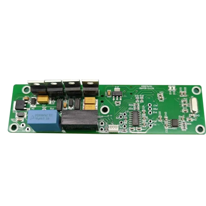
1. Why Thermal Stability Is a Manufacturing Outcome
A temperature controller is often evaluated by its setpoint accuracy on a datasheet, but field behavior is governed by physical variables that are introduced during assembly. Solder voids increase thermal resistance. Contamination creates leakage paths that shift analog readings. Copper distribution near the sensor can turn the board itself into a heat spreader. Each of these conditions is a manufacturing signature, not a software problem.
The difference between a controller that holds ±0.5 °C and one that drifts by several degrees is frequently traced to process discipline. A study of precision thermal control boards shows that power traces carrying several amperes must be sized with sufficient copper and kept physically separated from the sensor return path; otherwise, localized heating and IR drop corrupt the measurement before the signal reaches the ADC. In the same way, thermal relief cuts, narrow sensor traces, and deliberate spacing from high-current components create a "thermally honest" zone around the sensing element so that it responds to the system temperature rather than the board's internal heat flow.
This is why the phrase Temperature controller PCBA describes more than a populated board. It describes a controlled thermal system whose measurement chain, power stage, and protection circuitry are co-designed and co-manufactured. When the assembly process is unstable, the control loop is forced to compensate for physical noise it cannot see.
Key principle: The sensor does not measure the environment directly. It measures the local thermal state of the PCB. Manufacturing determines whether that local state is representative or distorted.
2. Sensor Interface: The First Line of Defense
2.1 Sensor Type and Its Manufacturing Implications
NTC thermistors, PT100/PT1000 RTDs, and thermocouples impose different constraints on the PCB front end. NTC sensors deliver high sensitivity in narrow bands but require linearization because their resistance-temperature curve is exponential. RTDs offer a more linear response over wide ranges, but their low-resistance signal path is more sensitive to trace resistance and soldering-induced stress. Thermocouples provide the widest range but the lowest accuracy, often in the range of several degrees, and depend on cold-junction compensation that must be electrically stable.
The sensor front end is not just an analog input; it is a high-impedance measurement node that must reject common-mode noise while preserving a small differential signal. Typical commercial controllers illustrate the spread: an NTC input may be rated at ±0.6 °C, a PT100 channel at ±0.7 °C, and a J-type thermocouple at ±3 °C. These figures are sensor-level specifications, not system-level guarantees. The assembly process either preserves that accuracy or erodes it through poor grounding, thermal gradients, and inadequate calibration access.
2.2 Layout Isolation and Calibration Access
A sensor trace that runs beside a relay driver or a MOSFET switching node will couple noise into the measurement. A ground plane that is interrupted under the analog front end will force return currents through shared copper, creating offsets that vary with load. During design-for-manufacturing review, these issues should be flagged before tooling is released. The engineering review must assess thermal coupling, component placement for sensor isolation, and power/ground plane integrity for clean analog sensing and stable PWM switching.
Calibration is the final bridge between the sensor and the physical enclosure. No sensor is perfectly matched to a specific PCB, housing, and assembly stack. A one-time calibration in a controlled thermal chamber applies a corrective offset, but the board must be designed with test access and firmware hooks that make this calibration repeatable. If the PCBA is assembled with inconsistent solder volume or contamination, the calibration offset will drift with age and temperature, defeating the purpose of the initial correction.
3. PCB Materials and Copper Architecture Under Heat
Temperature controllers often operate in enclosures where ambient temperature rises well above room level, and the power stage adds its own heat. The substrate must maintain dimensional stability and dielectric integrity across that range. FR-4 is common, but high-Tg laminates and aluminum substrates are selected when the thermal load or the cycling profile exceeds what standard FR-4 can tolerate without measurable shift.
The weave pattern of the fiberglass cloth inside FR-4 can cause localized variations in thermal conductivity, leading to "thermal weave" effects that shift the sensor reading depending on where the trace is routed. This is especially important for high-precision controllers where even a 0.1 °C deviation matters. Copper architecture is equally important. A 2-layer board may be adequate for a simple thermostat, but controllers with mixed-signal front ends and PWM outputs benefit from 4-layer or 6-layer stackups with dedicated ground planes adjacent to signal layers. This arrangement provides inherent isolation between the noisy power section and the sensitive analog section, reducing the need for external filtering that can itself drift.
| Design Variable | Stability Benefit | Manufacturing Risk if Ignored |
|---|---|---|
| Layer count and ground plane | Dedicated analog return path; reduced common-impedance coupling | Sensor readings shift with relay or MOSFET switching |
| Power trace width and copper weight | Lower IR drop and localized heating at high current | Hot spots near the sensor; thermal offset that changes with load |
| Thermal relief and spacing | Sensor responds to ambient, not to conducted heat from power copper | Controller regulates the board instead of the process |
| Board thickness and substrate | Dimensional stability across cycling; consistent CTE behavior | Solder stress, warpage, and layer-to-layer misalignment |
The physical stackup is therefore not a passive backdrop. It is part of the control loop. A board that distributes heat unevenly will produce a sensor signal that is electrically accurate but thermally false.
4. Solder Joint Reliability Across Thermal Cycles
Temperature controllers are exposed to repeated heating and cooling. The solder joints that connect power devices, relays, and sensor connectors must survive the resulting thermomechanical stress. The dominant mechanism is CTE mismatch: silicon, copper, solder, and laminate expand at different rates, and over many cycles the mismatch concentrates strain at the joint interface. Micro-cracks initiate at the periphery of the joint and propagate until resistance rises or the connection opens.
This failure mode is especially relevant around MOSFETs, TRIACs, and relay terminals, where localized temperature excursions are largest. A controller that passes a room-temperature functional test can still fail after several hundred cycles if the solder process has produced voids, insufficient wetting, or excessive intermetallic formation. The assembly response must therefore include controlled reflow profiles, verified paste deposition, and inspection methods that can see hidden joints.
- Reflow uniformity: A delta T of roughly 10 °C between the hottest and coldest joint on a panel is a practical target for many lead-free profiles; wider spreads mean some joints are under-processed while others are over-stressed.
- Void control: Voids under thermal pads increase junction-to-board resistance and create local hot spots that accelerate crack growth.
- Inspection access: X-ray inspection is necessary for BGA and bottom-terminated components; AOI alone cannot confirm hidden joint geometry.
- Strain relief: Connectors and heavy through-hole parts should be mechanically supported so that thermal expansion of the housing is not transferred directly into the solder fillet.
Every Temperature controller PCBA that is expected to operate for years in a cycling environment must be built with a solder process that is qualified against thermal cycling, not just against visual acceptance criteria. IPC-A-610 Class 2 or Class 3 provides a baseline for workmanship, but the cycling behavior of the joint is determined by the combination of alloy, profile, and pad design.
5. Test Coverage That Exposes Latent Thermal Defects
Functional testing at room temperature is necessary but insufficient for a thermal controller. A board can pass in-circuit test and functional circuit test and still contain a latent defect that appears only under temperature stress. The test strategy should escalate in stress level so that early-life failures are precipitated before shipment.
Automated optical inspection verifies component presence and solder fillet shape. In-circuit test confirms resistor and capacitor values and detects shorts or opens. Functional circuit test simulates sensor inputs and validates relay or SSR outputs. X-ray inspection reveals hidden solder voids and BGA collapse. Burn-in and environmental stress screening then subject the assembly to elevated temperature under load cycling, often for 24 to 48 hours, to force marginal joints and component defects to fail. Environmental chambers extend this capability from −40 °C to +125 °C and 0–95% relative humidity, allowing the manufacturer to correlate bench behavior with field conditions.
Test fixture contact resistance can also mask a marginal joint. If the pogo pins do not make consistent contact, the test may pass a board that would fail under vibration or thermal expansion. Burn-in is not a substitute for a stable process. It is a filter for specific risks, and it is most effective when the stress profile reflects the actual thermal mission of the controller. A generic high-temperature soak may consume test capacity without revealing the cycling-related weaknesses that matter in a temperature control application.
6. Conformal Coating and Environmental Isolation
Moisture and contamination are thermal problems in disguise. A thin film of adsorbed water on a PCB surface can create leakage paths between sensor traces, changing the effective resistance of the measurement network. Chemical residues from flux or handling can become conductive when humidity rises. In a controller that relies on a high-impedance sensor input, these leakage paths appear as temperature offset or noise.
Conformal coating addresses this by forming a thin polymer layer that conforms to the board topology and isolates the circuitry from moisture, dust, and chemical contaminants. Acrylic coatings are economical and reworkable; polyurethane offers better solvent and abrasion resistance; silicone provides the widest temperature range and flexibility. The coating must be applied after thorough cleaning, because encapsulating ionic contamination traps it against the board and can accelerate electrochemical failure rather than prevent it.
Coating adhesion is another variable; if the surface energy is too low due to residue, the coating may delaminate during thermal cycling, opening a path for moisture. Selective coating is often preferable for temperature controllers because connectors, relays, and test points may need to remain uncoated. The process must be controlled so that coating thickness is sufficient on exposed traces but does not bridge fine-pitch leads or interfere with thermal relief features.
7. Traceability as a Thermal-Risk Control Tool
When a controller drifts in the field, the first question is whether the behavior is isolated or batch-related. Without traceability, that question cannot be answered efficiently. Lot-level and unit-level traceability link each serial number to component date codes, reflow records, test results, and coating batch. This allows the manufacturer and the customer to determine whether a drift complaint correlates with a specific component lot, a specific line, or a specific environmental test excursion.
Traceability in a Temperature controller PCBA program is not administrative overhead. It is the mechanism that turns a field failure into a bounded, correctable event instead of an open-ended reliability question. Authorized sourcing is the other half of traceability. Components purchased through franchised distributors carry documented provenance. Components from open market channels may be refurbished, relabeled, or outside the specified date code window. For a temperature controller, a counterfeit or aged sensor interface component can shift the entire measurement chain. Visual, electrical, and X-ray validation of incoming components provides a practical anti-counterfeit barrier before assembly begins.
Manufacturing note: Traceability is not paperwork. It is the only way to distinguish a random field event from a systematic process shift that requires immediate containment.
8. From Prototype to Volume: Manufacturing Maturity
Thermal stability must survive the transition from engineering samples to volume production. A process that works on five boards may behave differently on five thousand if paste deposition, reflow loading, or test fixture contact changes. The manufacturing partner must demonstrate that the same controlled parameters are maintained across each phase.
- Engineering verificationSmall builds for design validation and initial thermal tuning. Focus on layout verification and sensor calibration access.
- Pilot runProcess characterization and thermal stress testing. Solder profile, coating coverage, and test limits are fixed.
- Low-volume productionMarket-entry batches. Traceability and incoming inspection discipline are exercised at scale.
- High-volume productionStable SMT yield, repeatable functional test, and batch-level reliability monitoring.
At each stage, the manufacturer should provide design-for-manufacturing feedback that addresses thermal relief on power traces, component spacing, and test point accessibility. A partner with IATF 16949 discipline applies advanced quality planning, failure mode analysis, and change control to the thermal controller program, even when the end product is industrial rather than automotive. ISO 13485 adds unit-level traceability, process validation, and risk-management documentation for medical-grade controllers. These frameworks are not marketing labels; they determine whether the manufacturing process is capable of holding a thermal specification over time.
Unixplore Electronics applies this layered approach—sensor-aware DFM, in-house AOI, ICT, FCT, X-ray, burn-in, and environmental screening—to bridge design intent and volume reliability. A double-sided SMT first-pass yield above 98.5% is one indicator, but the more meaningful outcome is a controller whose thermal behavior remains inside its specification after repeated cycling and field exposure.
9. Frequently Asked Questions
Does a higher layer count always improve thermal stability?
Not automatically. A 4-layer or 6-layer stackup with a dedicated ground plane generally provides better isolation between power and analog sections than a 2-layer board, but the benefit depends on how the planes are partitioned and where the sensor traces are routed. A poorly partitioned 4-layer board can perform worse than a carefully routed 2-layer design.
Why is burn-in necessary if AOI and functional test already pass?
AOI and functional test catch defects that are visible or electrically present at the time of test. Burn-in accelerates early-life failures by applying temperature and load cycling, exposing marginal solder joints, component weaknesses, and intermittent connections that a single-pass test may miss. It is a reliability filter, not a replacement for process control.
Can conformal coating compensate for a poor cleaning process?
No. Coating over ionic contamination can trap moisture and accelerate failure. The board must be cleaned and dried before coating so that the polymer layer protects a chemically benign surface rather than sealing contaminants against it.
How does traceability help if the controller has already drifted in the field?
Traceability links the affected unit to its component lots, reflow records, and test history. This allows the manufacturer to determine whether the drift is an isolated event, a batch-related material issue, or a process excursion, and to bound the corrective action rather than treating every unit as suspect.
What is the most common manufacturing cause of sensor offset in a temperature controller?
Thermal coupling from power copper into the sensor region, combined with insufficient calibration access. If the sensor trace is routed near a heat-generating component or shares a return path with high-current circuitry, the measured temperature will include a load-dependent offset that cannot be removed by firmware alone.
The difference between a controller that holds its specification and one that drifts is built into the process. Share your Gerber files, BOM, sensor type, and annual volume to receive a manufacturing review focused on thermal stability, test coverage, and traceability.
Contact us to discuss your temperature controller program and receive a technical response from the engineering team.
Contact Us