- English
- Español
- Português
- русский
- Français
- 日本語
- Deutsch
- tiếng Việt
- Italiano
- Nederlands
- ภาษาไทย
- Polski
- 한국어
- Svenska
- magyar
- Malay
- বাংলা ভাষার
- Dansk
- Suomi
- हिन्दी
- Pilipino
- Türkçe
- Gaeilge
- العربية
- Indonesia
- Norsk
- تمل
- český
- ελληνικά
- український
- Javanese
- فارسی
- தமிழ்
- తెలుగు
- नेपाली
- Burmese
- български
- ລາວ
- Latine
- Қазақша
- Euskal
- Azərbaycan
- Slovenský jazyk
- Македонски
- Lietuvos
- Eesti Keel
- Română
- Slovenski
- मराठी
- Srpski језик

Radar Detector PCBA: Bridging the Gap Between Design and Production – Our Expert Guide
At Unixplore Electronics Co., Ltd., we've spent years at the forefront of radar detector PCBA manufacturing. Working with clients across automotive, security, and industrial sensing applications, we've seen one challenge repeatedly trip up even the most experienced engineering teams: the frustrating gap between a working reference design and a production-ready PCBA that performs consistently in the real world.
You've likely been there. The reference board runs beautifully in the lab. Your custom PCB? Shorter detection range. Wild unit-to-unit variation. Or worse—EMC certification failures that send you back to square one.
These problems aren't bad luck. They're the predictable outcome of underestimating what it takes to design and manufacture high-frequency circuits at scale. Drawing from our hands-on experience as a dedicated Radar Detector PCBA manufacturer, we'll walk you through the real challenges and—more importantly—show you how to solve them, step by step.
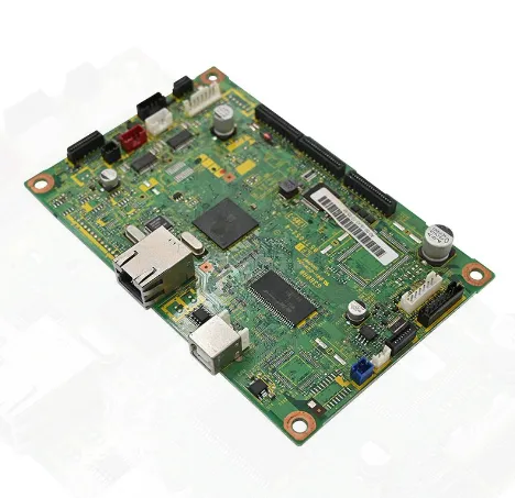
The Root Causes: Why Radar PCBAs Underperform
A radar PCBA operates at microwave frequencies—24GHz, 60GHz, or even 77GHz. At these frequencies, the PCB substrate stops being a passive interconnect and becomes an active part of the RF circuitry. This fundamental shift introduces failure modes that simply don't exist at lower frequencies.
Here's what we've seen derail projects time and again:
-
Batch-to-Batch Inconsistency: Using the exact same design files, different production runs can produce ADC amplitude variations of 10–15%. We've traced this to manufacturing tolerances—trace width, copper spacing, and dielectric constant (Dk) fluctuations—that directly alter RF trace impedance. Without tight process controls, your "identical" boards won't perform identically.
-
Custom Boards vs. Reference Designs: The chip is the same. The configuration is the same. Yet your board's detection angle is noticeably narrower than the evaluation module's. In our experience, this usually points to poor RF isolation between the radar chip (especially AIP—Antenna-in-Package—devices) and the PCB ground plane. The ground layer ends up reflecting or re-radiating energy, distorting the radiation pattern.
-
EMC/EMI Certification Nightmares: Radar products must pass FCC, CE, and other regulatory standards. If EMC/EMI isn't baked into the design from day one, retrofit fixes are expensive and often inadequate. We've rescued more than a few projects where last-minute "fixes" only made things worse.
-
Field Failures: A board that passes all lab tests can still fail in the field. Temperature swings, vibration, power supply noise, and humidity expose weaknesses that bench testing never catches. This is why environmental reliability must be part of your design and test strategy from the beginning.
Our Step-by-Step Guide to Building a Reliable Radar Detector PCBA
Over the years, we've developed a systematic approach that consistently delivers radar PCBAs that perform as designed—batch after batch. Here's our playbook.
Step 1: Choose the Right Substrate – It's Not Optional
At millimeter-wave frequencies, substrate selection is make-or-break. Standard FR-4? It's fine for 100MHz. At 24GHz and above, its high loss tangent (Df) and unstable dielectric constant (Dk) will cripple your performance.
What we look for:
-
Dk (Dielectric Constant) – Determines impedance consistency. Variation here means variation in performance.
-
Df (Dissipation Factor) – Higher Df equals higher insertion loss. At high frequencies, even small differences matter.
- Our material recommendations:
-
Rogers 4350B (Dk 3.5, Df 0.0037) – Our go-to for 24GHz and 77GHz designs. Excellent balance of RF performance and cost-effectiveness.
-
Rogers 4003C (Dk 3.4, Df 0.0027) – Lower loss, superb batch-to-batch stability. Ideal when consistency is your top priority.
-
Rogers RO3003 (Dk 3.0, Df 0.0013) – Ultra-low loss for the most demanding millimeter-wave front-ends.
Cost-conscious approach: For projects with budget constraints, we often recommend hybrid stack-ups—using high-frequency materials (like Rogers) only in the RF-critical layers, with FR-4 elsewhere. It works, but requires careful evaluation of the fabrication process.
Pro tip from our factory floor: We maintain regular stock of these high-frequency materials. This isn't just about convenience—it shortens lead times and eliminates material variability from one order to the next.
Step 2: Master the Layout – RF Is a Discipline, Not a Mystery
RF layout often feels like black magic. But with discipline and experience, it becomes predictable science. Here are the rules we never break:
-
Strict Impedance Control: RF traces must be controlled to 50Ω single-ended (100Ω differential). We target ±8% tolerance—tighter than the industry-standard ±10%. This requires close collaboration with your PCB fabricator and, critically, impedance test reports for every batch.
-
Decoupling Capacitors Go as Close as Possible: Radar chips use LDOs that require external capacitors for compensation. Place these caps right next to the BGA balls. Even a few millimeters of extra trace length adds parasitic inductance that destabilizes the power delivery network. We've debugged more "mystery" failures caused by lazy cap placement than we can count.
-
Never Split the Ground Plane: The ground plane must be continuous and unbroken beneath RF sections. A split ground plane creates a longer, inductive return path—and worse, acts like an antenna that radiates noise. If you must route signals across the ground plane, think twice. Usually, you shouldn't.
-
Power Traces Must Carry Current Safely: This seems basic, but we regularly see designs where 1A power traces are too narrow. Our rule: use at least 16mil (0.4mm) width for 1A current. Anything thinner introduces voltage drop and thermal issues.
-
AIP Antenna Isolation: If your radar chip uses an Antenna-in-Package (AIP) design, pay special attention to the clearance between the antenna and the PCB ground plane. Increasing the height to the first ground layer—or adding parasitic structures—can dramatically reduce ground-plane reflections that distort your radiation pattern.
Step 3: Manufacture with Discipline – Consistency Is Everything
A brilliant design is worthless if you can't manufacture it reliably. This is where many projects stumble, and where our investment in advanced production capabilities pays off.
Our manufacturing standards:
-
Advanced SMT/DIP Capability: We're equipped to handle 0201 passives and 0.4mm-pitch BGA/QFN packages. If your fabricator can't do this, walk away.
-
IPC Compliance: We follow IPC-6012 (rigid PCB qualification) and IPC-A-610 (acceptability of electronic assemblies) as non-negotiable baselines.
-
100% RF Functional Testing (FCT): This is critical. AOI and ICT catch solder and connectivity issues, but they don't measure RF performance. We test every single board for detection range, sensitivity, and signal strength. This is how we catch—and eliminate—batch-to-batch variation before boards ever ship.
Power management for battery-powered designs: For smart locks, sensors, and IoT radar detectors, sleep-mode power consumption is a key battleground. Our designs leverage PMICs with ultra-low quiescent current and carefully optimized power topologies to achieve microamp-level sleep currents.
Step 4: Learn from Others' Mistakes – And Our Experience
You don't have to make every mistake yourself. Here's what we've learned from thousands of radar projects:
-
Start with the Reference Design—But Understand Why It Works: Reference designs from TI, Infineon, NXP, and others exist for a reason. They're proven. We treat them as our starting point, not a suggestion. When we propose modifications—whether adding an isolator or changing a capacitor value—we validate every change with simulation and prototype testing.
-
Watch Out for "Small" Changes: We once saw a design where adding a 12pF decoupling capacitor on an SPI line caused ADC amplitude anomalies. The root cause? Ground bounce and cap placement, not the capacitor itself. The lesson: treat every change as significant until proven otherwise.
-
When in Doubt, Start with a Module: If your team is new to RF design, consider starting with an established radar module (like 24GHz designs based on ICL1112 or similar). These modules have already solved the antenna, RF front-end, and baseband challenges. You can integrate them into your system with much lower risk.
Send Inquiry
-
Delivery Service



-
Payment Options