- English
- Español
- Português
- русский
- Français
- 日本語
- Deutsch
- tiếng Việt
- Italiano
- Nederlands
- ภาษาไทย
- Polski
- 한국어
- Svenska
- magyar
- Malay
- বাংলা ভাষার
- Dansk
- Suomi
- हिन्दी
- Pilipino
- Türkçe
- Gaeilge
- العربية
- Indonesia
- Norsk
- تمل
- český
- ελληνικά
- український
- Javanese
- فارسی
- தமிழ்
- తెలుగు
- नेपाली
- Burmese
- български
- ລາວ
- Latine
- Қазақша
- Euskal
- Azərbaycan
- Slovenský jazyk
- Македонски
- Lietuvos
- Eesti Keel
- Română
- Slovenski
- मराठी
- Srpski језик

How Dash Cam PCBA Development Is Evolving: From Chip Selection to Mass Production
At its core, a dash cam is defined not by its lens or housing, but by its PCBA (Printed Circuit Board Assembly). Get the chipset right and the board stable, and you’ve already won half the battle. Drawing from real-world industry experience, here is a straightforward guide covering chipset selection, circuit design, manufacturing, and testing.
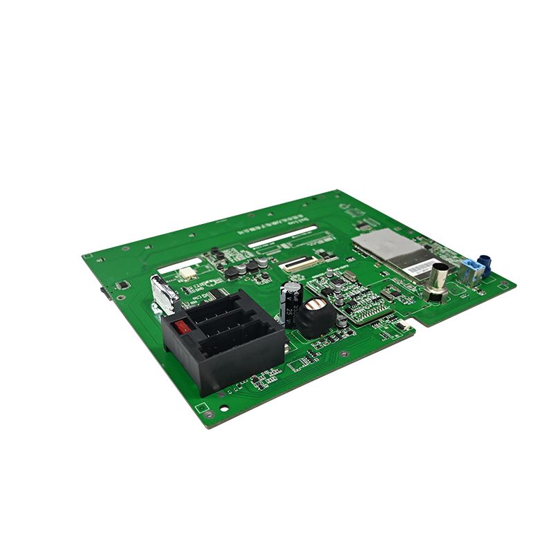
1. Chipset Selection: Choose the "Brain" First, Then Build Around It
The main processor is the heart of the PCBA. Once this is decided, the rest of the circuit, cost, and performance ceiling are largely set. Currently, the mainstream options each have their own strengths:
-
Ambarella: Known for superior image processing, excellent image quality, and high encoding efficiency. Ideal for high-end 4K dash cams, but development is complex and BOM costs are higher.
-
Novatek: The market leader in terms of volume. Offers excellent value for money, with options ranging from entry-level to high-end (supporting 4K, HDR). Often the top choice for mass-produced products.
-
Others (Hisilicon, Allwinner, etc.): Used in specific markets or cost-sensitive products.
Don’t just look at the resolution. Assess your actual needs: Does it support front-and-rear dual recording? How is low-light performance? Do you need ADAS or AI features? These determine the required computing power and ISP (Image Signal Processor) capabilities.
Once the main processor is chosen, pay attention to these key peripherals:
-
Power Management: Automotive power is notoriously noisy (9V–16V with transient spikes). You must use a wide-input voltage DC-DC converter with over-voltage, over-current, and reverse-polarity protection. If parking mode is required, add a low-voltage detection/protection circuit to prevent draining the car battery.
-
Image Sensor: Sony IMX series (e.g., IMX335) is a common choice. Ensure the MIPI CSI interface matches well with the main processor.
-
Storage: Use eMMC for firmware storage and a TF card slot for video storage. The card slot must have ESD protection.
2. Circuit Design Essentials: Anti-Interference and Thermal Management Are Key Challenges
Dash cams sit on windshields, baking in summer sun and freezing in winter, all while enduring constant vibration. This demands extremely high stability and reliability from the PCBA. Two critical issues must be addressed at the design stage:
2.1 Thermal Management (Heat Dissipation)
During 4K video recording, the processor and sensor generate significant heat within a sealed enclosure. Poor thermal management leads to system crashes, image artifacts, and accelerated component aging. Effective solutions include:
Large copper pours under the main processor, with dense thermal vias connecting to inner and bottom copper layers to spread heat.Strategic component placement to distribute heat sources evenly and avoid localized hotspots.
Designing the PCBA to leverage the metal housing or dedicated heat spreaders for passive cooling.
2.2 Signal Integrity and EMI/EMC
High-speed signals (MIPI, DDR) and RF signals (Wi-Fi, GPS) are crowded onto a small board. Without careful design, interference causes image noise, frame drops, or signal loss.
Impedance Control: Calculate and strictly control 100Ω differential impedance for MIPI, USB, and other high-speed differential pairs, and 50Ω single-ended impedance for other critical traces.Length Matching: Differential pairs and DDR data groups must have strict length matching (within ±10 mils) to ensure proper timing.
Guard Tracing: Route ground traces alongside critical signals (clock, I2C, audio, video) and add stitching vias for isolation.
Layer Stackup: Use a 4-layer or 6-layer PCB with a solid ground plane and a solid power plane. Route high-speed signals on inner layers to use the planes as shielding.
Additionally, always place TVS diodes at input connectors for ESD protection, add ferrite beads and capacitors at the power input for filtering, and use single-point separation between analog and digital ground planes. These are simple but highly effective techniques.
3. Manufacturing and Quality Control: The Gatekeepers Before Mass Production
A good design is only half the story. To ship a reliable PCBA, thorough manufacturing and testing processes are non-negotiable.
-
SMT Assembly and AOI Inspection: Reputable factories use 3D SPI to inspect solder paste quality, high-speed pick-and-place machines for BGA and 0402 components, and AOI (Automated Optical Inspection) to detect soldering defects (bridging, cold joints, missing components).
-
FCT (Functional Circuit Test): Simulate actual dash cam operation by powering on the PCBA and testing every function: recording, audio, GPS signal acquisition, button response, and display output.
-
Burn-in Test (Aging Test): Run the PCBA continuously for several to tens of hours in a high-temperature, high-humidity chamber. This exposes latent defects (like intermittent solder joints or thermally unstable components) and is a critical step for ensuring long-term reliability.
Building a reliable dash cam PCBA is a systematic engineering effort. It’s a balancing act—finding the sweet spot between performance, cost, physical size, thermal dissipation, and long-term dependability. By addressing these practical considerations upfront, you can avoid many common pitfalls and streamline your path to a successful product launch.
Send Inquiry
-
Delivery Service



-
Payment Options