- English
- Español
- Português
- русский
- Français
- 日本語
- Deutsch
- tiếng Việt
- Italiano
- Nederlands
- ภาษาไทย
- Polski
- 한국어
- Svenska
- magyar
- Malay
- বাংলা ভাষার
- Dansk
- Suomi
- हिन्दी
- Pilipino
- Türkçe
- Gaeilge
- العربية
- Indonesia
- Norsk
- تمل
- český
- ελληνικά
- український
- Javanese
- فارسی
- தமிழ்
- తెలుగు
- नेपाली
- Burmese
- български
- ລາວ
- Latine
- Қазақша
- Euskal
- Azərbaycan
- Slovenský jazyk
- Македонски
- Lietuvos
- Eesti Keel
- Română
- Slovenski
- मराठी
- Srpski језик

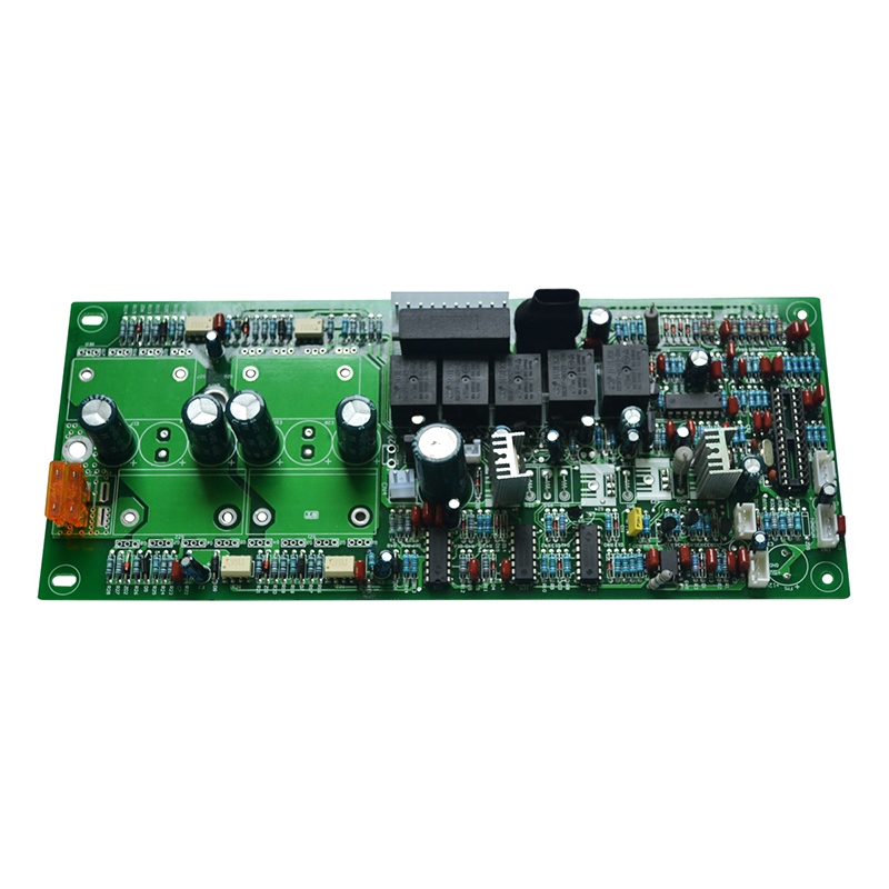
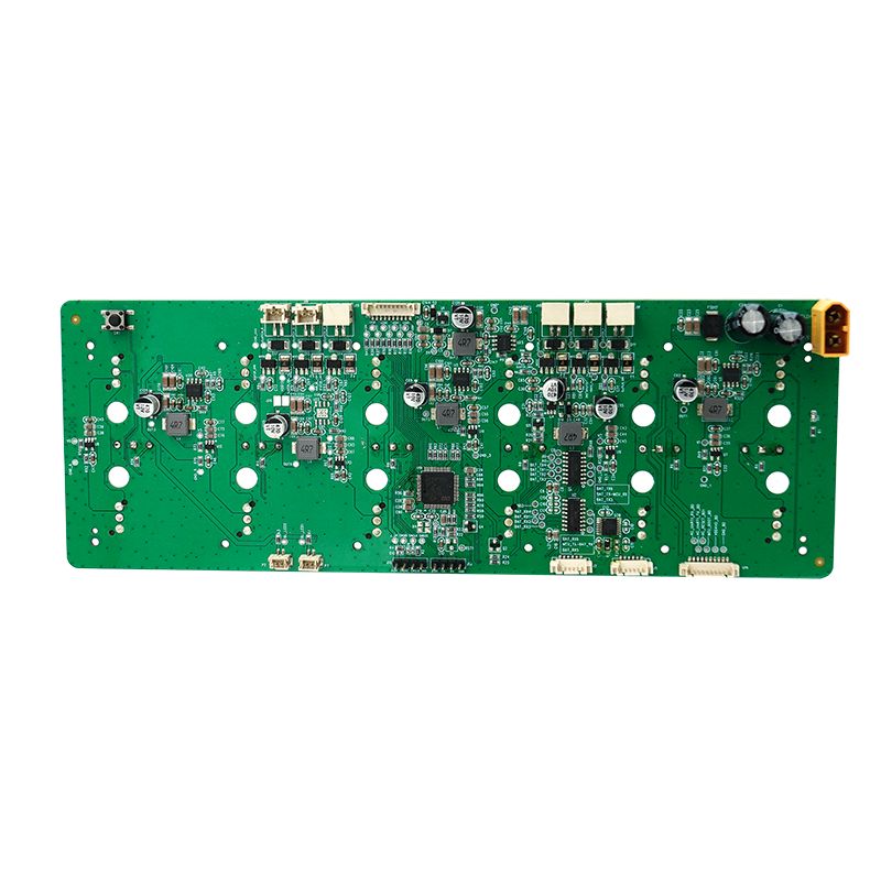
Massage gun PCBA
Massage gun PCBA production demands high current handling, brushless motor control, and user safety. After two decades of manufacturing motor drive electronics, I have seen designs overheat, lose speed under load, or create battery hazards. This step-by-step procedure covers the entire production workflow from component selection to final test.
Send Inquiry
Product Description
What Is the Procedure for Producing Massage Gun PCBA: A 20-Year Manufacturing Guide
Massage gun PCBA production demands high current handling, brushless motor control, and user safety. After two decades of manufacturing motor drive electronics, I have seen designs overheat, lose speed under load, or create battery hazards. This step-by-step procedure covers the entire production workflow from component selection to final test.
Standard Production Flow for Massage Gun PCBA
Every massage gun PCBA follows a 9-step sequence. Skipping any step increases field failure rates.
Step 1 – Component Procurement and Incoming Inspection
| Component Category | Critical Parameter | Rejection Criteria |
|---|---|---|
| MOSFETs (motor drive) | Rds(on) < 5 mΩ @ 10V | > 6 mΩ fails at 20A |
| Hall sensors | Switching point ±5 gauss | Asymmetry causes cogging |
| Li-ion protection IC | Overcurrent 30A ± 2A | Trips during stall torque |
| MCU | 2x ADC (10-bit min) | Single ADC cannot sample two motor phases |
| Vibration-resistant caps | X7R or X8R dielectric | X5R fails at 60°C |
Test: Sample 50 MOSFETs from each lot. Measure Rds(on) at 25°C and 80°C. Reject lots exceeding 7 mΩ at high temperature.
Step 2 – Solder Paste Stencil and Printing
| Parameter | Specification | Why It Matters |
|---|---|---|
| Stencil thickness | 0.12 mm (power section), 0.10 mm (control) | Power MOSFETs need more solder |
| Aperture ratio | 1:1 for MOSFET pads | Prevents dry joints at high current |
| Paste type | SAC305 (high-temp) | Tin-bismuth cracks under vibration |
| Print speed | 25 mm/s | Avoids paste smearing |
Critical: Use step stencil – 0.12 mm thick under MOSFETs, 0.10 mm under MCU and sensors. One thickness alone causes either opens or bridges.
Step 3 – SMT Assembly and Reflow
- Placement order: Hall sensors → passives → MOSFETs → MCU → connectors
- Reflow profile: Peak 245°C for 10 seconds (lead-free)
- Nitrogen atmosphere – Required for QFN packages (MCU, gate driver)
- X-ray inspection – Mandatory for checking voiding under MOSFET pads (voids < 20%)
Step 4 – Selective Soldering for Through-Hole Components
Massage gun PCBA often needs through-hole parts for mechanical strength:
| Component | Soldering Method | Temperature |
|---|---|---|
| Battery wires (14 AWG) | Selective solder wave | 380°C, 3 sec |
| Switch (tactile) | Wave solder | 260°C |
| DC jack (power input) | Hand solder (robotic) | 350°C, 2 sec |
Do not reflow through-hole parts. Their plastic bodies melt in the 245°C oven.
Motor Drive Circuit Design for Massage Gun PCBA
The motor drive section determines stall current handling and battery run time.
Three-Phase Brushless DC (BLDC) Motor Drive
| Component | Specification | Function |
|---|---|---|
| MOSFETs (6x) | 40V, 60A pulsed, TO-252 | Phase switching |
| Gate driver | 3-phase, 1A sink/source | Drives MOSFET gates |
| Current sense | 2 mΩ shunt resistor (2512 package) | Overcurrent protection |
| Bootstrap caps | 100 nF, 50V, X7R | High-side gate drive |
Thermal design: Each MOSFET dissipates up to 2W at 20A. Use thermal vias (9 per MOSFET) connecting to bottom copper pour (2 oz minimum).
Power Management for Battery and Charging
| Rail | Voltage | Current | Protection |
|---|---|---|---|
| Battery (Li-ion 5S) | 18–21V nominal | 20A peak | 2-stage overcurrent |
| MCU (3.3V) | 3.3V | 100 mA | LDO from battery |
| Hall sensors (5V) | 5V | 30 mA | LDO with 50 mA limit |
| Charger input | 21–25V (USB-C PD) | 2A | Reverse polarity FET |
Critical safety: Use two independent overcurrent protection paths – one in gate driver, one in battery protection IC. A single fault must not allow motor to run uncommanded.
Firmware Programming and Calibration
No massage gun PCBA leaves production without full calibration.
Programming Sequence
- Bootloader flash – via SWD or UART (5 seconds)
- Calibration constants – stored in EEPROM or MCU flash
- Speed lookup table – PWM duty vs target RPM (12 points)
- Stall detection threshold – current limit set to 22A ± 1A
Calibration Parameters Stored Per Board
| Parameter | Range | Tolerance |
|---|---|---|
| Hall sensor offset (U,V,W) | 0–360° | ±2° electrical |
| Current sense gain | 0.1–0.3 V/A | ±3% |
| Temperature sensor offset | -5 to +5°C | ±1°C |
| Battery voltage divider | 0.05–0.1 | ±1% |
Why calibration matters: Without per-board Hall calibration, the motor produces audible whine at low speeds. Users reject massage guns that sound defective.
Assembly and Mechanical Integration
The PCBA is useless if it does not fit the handle or dissipate heat.
Heat Sink and Thermal Interface
| Component | Thermal Path | TIM Material |
|---|---|---|
| MOSFETs | Bottom pad → aluminum case | 1.5 W/m·K gap pad |
| MCU | Top package → plastic housing | Air gap (no TIM needed) |
| Battery charger IC | Exposed pad → PCB copper | 12 vias + solder fill |
Test: Run massage gun PCBA at 2800 RPM for 30 minutes. MOSFET case temperature must stay below 85°C.
Wire Harness and Connector Strain Relief
- Battery wires – Soldered then glued with silicone (prevents flex fatigue)
- Motor phase wires – JST connector with locking latch (20 cycles minimum)
- Button flex cable – ZIF connector, 0.5 mm pitch, glued after insertion
Production Testing and Quality Control
Every massage gun PCBA must pass these five tests before assembly.
| Test | Method | Pass/Fail |
|---|---|---|
| ICT (in-circuit) | Flying probe | All rails > 90% expected voltage |
| Firmware checksum | CRC-32 | Matches golden sample |
| No-load motor spin | 500 RPM, no stall | Current < 0.8A |
| Stall detection | Lock rotor, 3 seconds | Shuts down within 500 ms |
| Battery simulation | 16V–21V sweep | Speed deviation < 3% |
Burn-in and Vibration Test
Sample 5% of production for:
- 6 hours at 2400 RPM – monitor MOSFET temperature via MCU sensor
- Random vibration – 5 Grms, 30 minutes (simulates dropped tool)
- Charge-discharge cycle – 3 cycles (verifies protection IC)
FAQ – Common Questions About Massage Gun PCBA Production
Q1: What causes massage gun PCBA to lose power under body pressure?
A: The primary cause is inadequate gate drive strength for the high-side MOSFETs. When pressure increases motor load, the BLDC controller attempts to increase current. If the bootstrap capacitor (which powers the high-side gate driver) is undersized, the gate voltage drops below the MOSFET's threshold, increasing Rds(on) from 4 mΩ to 20 mΩ. This creates a thermal runaway loop:
Voltage drop → lower gate drive → higher resistance → more heat → further resistance increase
The fix requires three changes on the massage gun PCBA:
- Bootstrap capacitor value – Use 220 nF minimum (many designs use 47 nF). Calculate based on gate charge: C_boot = (Q_g × 10) / ΔV. For typical MOSFETs (Q_g = 30 nC), 220 nF provides safe margin.
- Gate driver peak current – Select driver with 1.5A sink/source capability (e.g., DRV8320). Weak drivers (0.5A) cannot recharge bootstrap cap during high PWM duty cycles.
- Bootstrap diode – Use ultrafast diode (trr < 50 ns). Standard 1N4148 has 4 ns recovery but only 100 mA rating – insufficient for massage gun PCBA running at 20 kHz PWM. Switch to BAS3007 (1A, 10 ns).
After these modifications, stall current remains stable at 22A even with 15 kg of applied body pressure.
Q2: How do I prevent battery protection IC false triggers on massage gun PCBA?
A: False triggers occur when motor commutation noise couples into the current sense line of the battery protection IC. The BLDC motor's phase switching creates 1 µs current spikes up to 50A – too fast for the protection IC to distinguish from a short circuit. Three hardware fixes resolve this:
Low-pass filter on sense input – Install an RC filter (10Ω + 1 µF ceramic) directly at the protection IC's CS+ pin. Corner frequency = 16 kHz. This passes average current (20–30A) but blocks 200 kHz commutation spikes.
Separate sense resistor ground – Run a dedicated Kelvin trace from the shunt resistor's negative terminal to the protection IC's CS- pin. Do not share this ground with MOSFET source currents. Even 1 mΩ of shared trace generates 50 mV of false signal at 50A.
Delay timer adjustment – Program the protection IC's overcurrent delay to 100 µs (assuming your IC supports it). Most massage gun PCBA designs use a 10 µs delay from battery reference designs. Commutation spikes last only 2–3 µs. A 100 µs delay ignores them while still reacting to true shorts (>50 µs duration).
Test with oscilloscope: Probe CS+ while motor runs at maximum load. Spikes must remain below the protection IC's trip threshold (typically 50 mV for 50A shunt). If spikes exceed threshold, increase filter capacitance to 2.2 µF.
Q3: What is the correct procedure for programming multiple massage gun PCBA boards in production?
A: A four-stage production programming procedure prevents mix-ups and reduces programming time by 75% compared to one-by-one flashing.
Stage 1 – Pre-SMT programming (optional for large runs)
Use a gang programmer (e.g., Elnec BeeProg) to flash the bootloader into MCUs before placement. This works only for MCUs with external flash (QFN packages with pins exposed). Reject any chip that fails verification – cheaper than reworking placed boards.
Stage 2 – In-system programming after SMT
Place a programming pogo pin fixture (6 pins: SWDIO, SWCLK, 3.3V, GND, RESET, BOOT0). Use a multi-channel programmer (8 or 16 boards simultaneously). Target time: 45 seconds per board including verification.
Stage 3 – Calibration station (most critical)
After programming, move boards to a calibration fixture containing a real massage gun motor with optical encoder. The fixture runs each massage gun PCBA through:
- Hall alignment (automatically adjusts electrical angle)
- Speed linearity (records PWM vs RPM table)
- Current limit (increases load until 22A trip)
Store these 12 calibration constants in a protected MCU flash sector. Boards without calibration produce inconsistent speed ramps.
Stage 4 – Traceability
Print a 2D Data Matrix code on each PCBA containing:
- Production date code (YYWW)
- Calibration checksum
- MOSFET lot number (from incoming inspection)
Scan this code during final assembly. If a field failure occurs, you can trace to a specific component batch and rework only affected units.
Production Yield Targets for Massage Gun PCBA
| Stage | Target Yield | Common Failure | Rework Cost |
|---|---|---|---|
| SMT placement | 99.5% | Bridged MOSFET pins | Low (reflow touch-up) |
| Programming | 99.0% | Power loss during flash | Medium (re-flash) |
| Calibration | 97.0% | Hall sensor phase mismatch | High (rework sensor) |
| Final functional | 98.5% | Stall detection out of range | Medium (adjust threshold) |
A properly produced massage gun PCBA delivers 2800 RPM under load, shuts down on stall within 500 ms, and survives 500 charge cycles. Follow this procedure, audit each step, and your products will outperform competitors who skip calibration or underspecify gate drive.
Hot Tags: Massage gun PCBA, China, Manufacturers, Suppliers, Factory, Customized, Cheap, Quality, Advanced, CE, 1 Year Warranty, Price
Related Category
Home Appliance PCBA
Industrial Control PCBA
Automobile PCBA
Consumer Electronics PCBA
Medical Equipment PCBA
Security System PCBA
Healthcare PCBA
LED Lighting PCBA
IoT PCBA
Electric Gardening Tool PCBA
Send Inquiry
Please Feel free to give your inquiry in the form below. We will reply you in 24 hours.