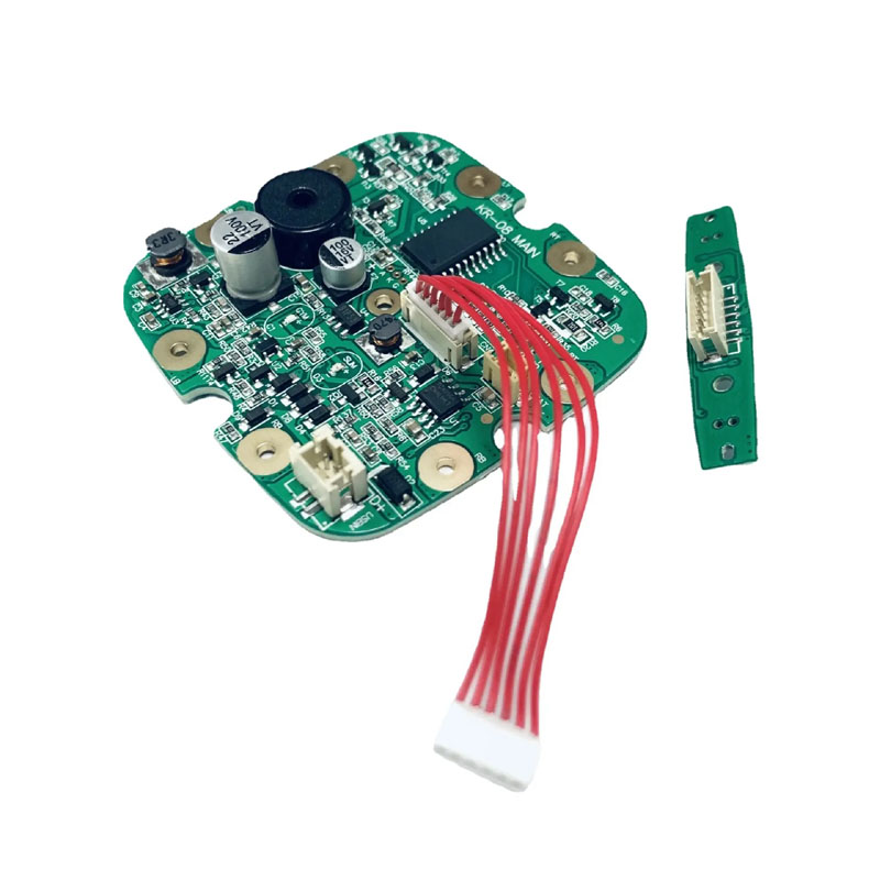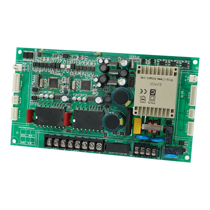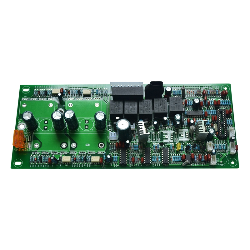
Core Reliability Requirements for Baby Monitor PCBA
Reliability starts with specifications. Do not guess infant room conditions.
Environmental and Operational Parameters
ParameterRequired SpecWhy It MattersOperating temperature0°C to 45°CNursery heaters and open windowsHumidity tolerance10%--90% non-condensingHumidifiers and droolContinuous runtime72 hours minimumParents forget to chargeDrop survival1.5 m onto carpetToddlers throw unitsRF duty cycle<1% for baby unitLow EMI near crib
Power Architecture for 24/7 Operation
Power RailComponentReliability FeatureBattery chargerLinear charger with thermal regulationPrevents lithium fire3.3V digitalDC-DC (2 MHz switching)Keeps noise above audio band3.0V RFUltra-low noise LDO (10 µVrms)No spurs on 2.4 GHz1.8V coreLDO with current limitMCU protection from short
Critical: Add a supercapacitor (0.47F, 5.4V) after the battery protection IC. This allows 10 seconds of recording after low-battery shutdown.
Component Selection for High MTBF
Mean Time Between Failures (MTBF) for a baby monitor PCBA should exceed 50,000 hours. Below are proven choices.
Wireless Chipset and Antenna
Choose a chipset with:
- Integrated PA (output power ≤ +10 dBm to meet infant safety standards)
- Listen-before-talk (avoid interference with cordless phones)
- Frequency hopping (40+ channels)
Chipset FamilyAdvantageDisadvantageNordic nRF52 SeriesLow sleep current (0.5 µA)Limited video bandwidthSilicon Labs EFR32Excellent ADC for audioLarger package (QFN48)Texas Instruments CC26xx-40°C to +85°C ratingRequires external balun
Antenna choice: Use a meandered inverted-F antenna (MIFA) on the PCBA edge. Keep 10 mm clearance from metal objects (speaker magnets, battery packs).
Audio Input and Processing
ComponentSpecificationReliability NoteMicrophoneMEMS, -38 dBV sensitivitySilicone cover for drool resistancePreamplifierGain 40 dB, noise < 5 nV/√HzAC-coupled with 0.1 Hz HPF (remove rumble)VOX thresholdAdjustable from -40 to -10 dBFSDigital hysteresis (3 dB) prevents chatteringSpeaker ampClass-D, 1.5 W into 8ΩFerrite bead on output leads (reduce EMI)
Temperature Sensing (Critical Safety Feature)
Place a thermistor (NTC, 10 kΩ at 25°C) on the baby unit PCBA near the charging IC. Firmware must:
- Log temperature every 30 seconds
- Shut down charging at 50°C
- Send wireless alert to parent unit at 45°C
PCB Layout for Low RF Leakage and Audio Quality
A noisy baby monitor PCBA causes static and dropouts. Follow these rules.
Layer Stack and Grounding
LayerFunctionConstraintTopRF (antenna feed, chipset)Coplanar waveguide with groundInner 1Continuous groundNo splits under RF sectionInner 2Power (3.3V, 1.8V)Island under each LDOBottomAudio, buttons, LEDsKeep digital traces away from mic input
Rule: Place a 0.1 µF capacitor at every power pin. Use 0402 size for low inductance.
Audio Ground Isolation
Digital ground and analog ground must meet at a single point under the codec. Use ferrite beads (600Ω at 100 MHz) between ground planes but only after verifying no ground loops.
Check with oscilloscope: Probe microphone output while transmitting RF. Noise should stay below 2 mV peak-to-peak.
Validation and Certification Checklist
Before production, test every baby monitor PCBA against these six standards.
TestMethodPass/Fail CriteriaAudio dropoutWalk 30 meters away with 3 walls< 3 dropouts per minute lasting >100 msBattery runtimeContinuous VOX at 65 dB SPL> 70 hours for 2000 mAh batteryCharge safetyShort battery terminalsPCBA enters hiccup mode, no component over 70°CRF coexistenceOperate beside WiFi router (2.4 GHz)No permanent desensitizationDrool resistanceSalt spray on microphone portAudio returns to normal after dryingOver-dischargeBattery voltage 2.8VMCU shuts down RF, keeps RTC
FAQ -- Common Questions About Reliable Baby Monitor PCBA
Q1: What is the most common hidden failure in baby monitor PCBA designs?
A: Microphonic noise from ceramic capacitors placed near the audio input path. When the baby unit vibrates (from a bassinet motor or dropped toy), class 2 dielectric caps (X7R, X5R) generate piezoelectric voltages up to 5 mV. This couples into the microphone preamplifier and produces audible clicks or rumbling. The solution is two-fold: 1) Use C0G (NP0) capacitors for all audio coupling and decoupling in the first gain stage. 2) If X7R is unavoidable, physically rotate the capacitor 90 degrees on the PCBA so mechanical stress aligns with the electrode direction. Always validate with a vibration table at 20 Hz, 1 Grms.
Q2: How does battery chemistry choice affect baby monitor PCBA longevity?
A: Three chemistries produce very different failure modes:
- Li-ion (18650): Highest energy density but requires precise CC/CV charging. A missing negative temperature coefficient (NTC) sensor leads to thermal runaway. Only use with authenticated battery packs containing protection IC.
- LiFePO4: Safer (no thermal runaway below 150°C) and longer cycle life (2000 cycles). However, lower voltage (3.2V nominal) demands a boost converter for 3.3V logic, adding cost and ripple noise.
- NiMH (low-cost designs): Very forgiving but suffers from memory effect. The PCBA must include a discharge circuit every 30 cycles to recalibrate fuel gauge. Without this, runtime drops 50% after 6 months.
For a reliable baby monitor PCBA, choose LiFePO4 for safety or quality Li-ion with dual over-voltage protection (IC + PTC).
Q3: Can I use the same PCBA design for both audio-only and video baby monitors?
A: No, and attempting this introduces three specific reliability problems:
- Memory bandwidth -- Audio-only needs 64 kB RAM. Video requires at least 2 MB for compressed frames. A shared PCBA with external RAM adds long traces that fail ESD testing.
- RF duty cycle -- Audio transmits 10% of the time. Video transmits 80% of the time. The same 2.4 GHz PA overheats in video mode, dropping gain by 6 dB after 20 minutes. You need a thermal via array under the PA for video designs.
- Power delivery -- Audio baby monitor PCBA peaks at 200 mA. Video peaks at 600 mA. A common PCB layout with thin power traces (0.25 mm) causes voltage droop that resets the camera module. Video designs require 0.6 mm traces or a separate 1A buck converter.
Build two separate PCBAs. Audio-only uses a 2-layer board. Video requires 4 layers with controlled impedance.
Production Testing for Zero Infant Risk
Every assembled baby monitor PCBA must pass:
Test StationDurationRejection CriteriaAudio loopback10 secondsTHD > 1% at 1 kHzBattery simulator30 secondsCharge current > 50 mA below 3.0VRF sensitivity5 secondsPacket error rate > 1% at -95 dBmOvertemperature60 secondsAny point > 60°C after full charge
Final Design Review Checklist
ItemConfirmationSchematicAll inputs have ESD protection (8 kV contact)BOMCapacitor voltage rating ≥ 2× expected (e.g., 10V for 5V rail)MechanicalNo tall components (height > 4 mm) near grip areasFirmwareWatchdog timer resets MCU if VOX hangs for > 5 minutesComplianceFCC Part 15 and EN 62368-1 (audio safety)
Designing a reliable baby monitor PCBA means prioritizing infant safety over cost reduction. A well-built board operates quietly through teething and tantrums. Test with real nursery conditions -- white noise machines, dimmer lights, and microwave ovens. That is the only way to earn parent trust.