- English
- Español
- Português
- русский
- Français
- 日本語
- Deutsch
- tiếng Việt
- Italiano
- Nederlands
- ภาษาไทย
- Polski
- 한국어
- Svenska
- magyar
- Malay
- বাংলা ভাষার
- Dansk
- Suomi
- हिन्दी
- Pilipino
- Türkçe
- Gaeilge
- العربية
- Indonesia
- Norsk
- تمل
- český
- ελληνικά
- український
- Javanese
- فارسی
- தமிழ்
- తెలుగు
- नेपाली
- Burmese
- български
- ລາວ
- Latine
- Қазақша
- Euskal
- Azərbaycan
- Slovenský jazyk
- Македонски
- Lietuvos
- Eesti Keel
- Română
- Slovenski
- मराठी
- Srpski језик


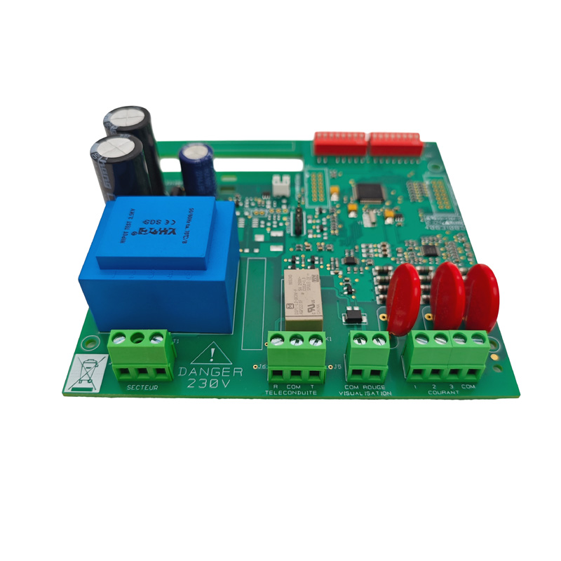
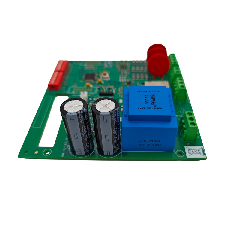
Fishing Sonar PCBA
Fishing sonar systems (fish finders) are core electronic systems for marine exploration and underwater imaging, primarily used for locating fish schools, measuring water depth, and imaging the seabed topography. As a professional one-stop PCBA manufacturer specializing in fishing sonar systems, we provide comprehensive services ranging from solution design, PCB fabrication, and SMT assembly to final unit assembly and functional testing.
Send Inquiry
Product Description
A fishing sonar system (fish finder) is the core electronic component in marine detection equipment, widely used in recreational fishing, commercial fishing, and underwater exploration. As a professional PCBA manufacturing service provider, we offer one-stop solutions from design to finished product assembly, ensuring reliable operation in harsh marine environments characterized by salt spray, high humidity, and extreme temperature fluctuations.
Two Core Assemblies of Fishing Sonar PCBA
The sonar system consists of two electronic assemblies, each with distinctly different PCBA requirements:
Display/Processor PCBA
-
Sonar signal processing – converting return echoes into digital images
-
GPS navigation integration – combining position data with sonar readings
-
Display driving – controlling LCD or touchscreen output
-
User interface interaction – reading button or touch inputs
Transducer PCBA
- Pulse generation – creating high-voltage bursts (±40V to ±100V) at sonar frequencies
-
Echo reception – amplifying and conditioning weak return signals (microvolt range)
-
Transmit/Receive switching – rapidly switching between transmit and receive modes
-
Impedance matching – matching cable and transducer characteristics
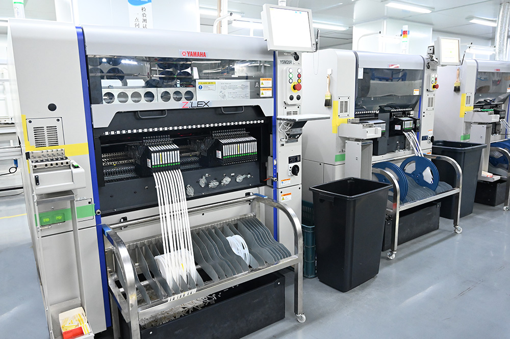
Modern Manufacturing Trend: High-end fishing transducers now use SMT technology, with pick-and-place machines mounting piezoelectric elements directly onto the PCBA, replacing manual positioning of ceramic crystals for improved accuracy and reduced cost.
Core Technical Specifications
| Parameter | Shallow Water (0-200ft) | Deep Water (200-1000ft+) |
|---|---|---|
| Typical Frequency | 200 kHz | 50 kHz or 38 kHz |
| Wavelength/Resolution | Shorter = higher detail | Longer = greater depth penetration |
| Transmit Power | 1 kW | 4 kW (commercial grade) |
| Transmit Voltage | ±40V to ±60V | ±80V to ±100V |
Available Configurations
-
Single frequency, single beam: 38 kHz, 50 kHz, 200 kHz @ 1 kW
-
Dual frequency, single beam: 38/200 kHz or 50/200 kHz (common for fishing)
-
High power: 4 kW deep-water commercial configuration
PCBA Physical Specifications
| Parameter | Display/Processor | Transducer Assembly |
|---|---|---|
| Board Material | FR4 (standard) | High-Tg FR4 or Flexible PCB |
| Layer Count | 4-8 layers | 2-4 layers |
| Copper Weight | 1-2 oz (signal), 2 oz (power) | 2 oz minimum (high current pulses) |
| Surface Finish | ENIG or OSP | ENIG (corrosion resistance) |
| Operating Temp | -20°C to +70°C | -40°C to +85°C |
| Conformal Coating | Recommended | Mandatory (marine environment) |
Six Critical Design Considerations
1. Signal Integrity – Ensuring Detection Accuracy
Sonar frequencies range from 50 kHz to over 900 kHz. PCBA layout directly affects detection range and accuracy:
-
Impedance-controlled traces: 50Ω or 75Ω typical for transducer cables
-
Matched trace lengths: For phased array transducers, all element traces must have identical electrical length
-
Guard rings: Surround sensitive analog inputs with grounded traces to reject noise
-
Separate analog/digital grounds: Connect at a single star point near the power input
2. Moisture Protection – The #1 Reliability Factor
Marine environments expose PCBAs to salt spray, condensation, and direct immersion. Conformal coating is non-negotiable:
| Coating Type | Best For | Pros | Cons |
|---|---|---|---|
| Acrylic (AR) | General marine use | Easy to apply, reworkable | Moderate chemical resistance |
| Silicone (SR) | Extreme temperature swings | Flexible, wide temp range (-55°C to +200°C) | Difficult to remove |
| Urethane (UR) | Prolonged saltwater immersion | Excellent chemical/salt resistance | Difficult to rework |
IP Rating Targets:
-
Display unit: IP65 minimum (dust-tight, water spray resistant)
-
Transducer assembly: IP68 minimum (immersion-proof to 1m+)
3. Transmit/Receive (T/R) Switching – Protecting the Sensitive Receiver
A sonar transducer cannot transmit and receive simultaneously. The PCBA must include a T/R switch that protects the sensitive Low-Noise Amplifier (LNA) from the high-voltage transmit pulse:
-
Three-layer protection: Chopper circuit + voltage clamping + series resistance
-
Response time: <10μs (1ft depth in shallow water = 2μs round trip)
-
Receiver protection rating: Survive ±100V peaks on a ±5V input
4. Power Amplifier Design
Boosts the MCU's logic-level signal (5V) to the voltage required to drive the transducer:
| Stage | Input | Output | Gain |
|---|---|---|---|
| Oscillator | MCU trigger pulse | 200 kHz, 500μs burst at 5V | N/A |
| MOSFET Driver | 5V logic | 12V gate drive | ~2x |
| Power MOSFETs | 12V switching | ±40V to ±60V sine wave (H-bridge) | ~8x |
5. Receiver Chain – Amplification and Filtering
Return echoes are extremely weak (millivolts or microvolts). The receiver chain requires high gain with low noise:
| Stage | Function | Typical Gain |
|---|---|---|
| Chopper (T/R protection) | Disconnects during transmit | N/A (pass-through) |
| Low-Noise Amplifier (LNA) | First-stage amplification (lowest noise floor) | 20-40 dB |
| Bandpass Filter | Removes out-of-band noise (200 kHz ±10 kHz) | -3 dB at cutoff |
| Secondary Amplifier | Brings signal to ADC range | 20-40 dB |
| Peak Detector | Converts RF envelope to DC for ranging | N/A |
6. Power Supply Design
Generates multiple clean voltage rails from a single 12V marine battery input:
| Rail | Current | Ripple Tolerance | Used For |
|---|---|---|---|
| 5V | 500mA-2A | <50mV | MCU, logic, display |
| 3.3V | 100mA-500mA | <30mV | DSP, ADC, precision analog |
| ±12V to ±15V | 100mA-500mA | <100mV | Op-amps, LNA |
| ±40V to ±100V | 1A-5A (pulsed) | N/A | Power amplifier (transmit only) |
Recommendation: Use separate switching regulators for digital and analog rails. Use LDOs after switching converters for the cleanest power to the receiver chain.
PCBA Layout Reliability Rules
| Rule | Key Points |
|---|---|
| Separate HV and LV Sections | Place power amplifier at one edge, receive circuitry at the opposite edge; minimum creepage distance 3mm between ±100V and 5V traces |
| Guard Sensitive Analog Inputs | Surround LNA input trace with grounded copper pour; add grounded vias every 5mm; keep input trace as short as possible |
| Stitch Ground Planes with Vias | 0.3mm vias at 5mm spacing connecting top and bottom ground planes; reduces ground impedance and prevents ground bounce |
| Bulk Capacitance Near Power Amp | Place 1000μF to 4700μF low-ESR capacitor at power amplifier supply input; prevents voltage collapse during transmit |
| Thermal Management for Power Stage | Use 2-3 oz copper for power traces; add minimum 9 thermal vias per MOSFET pad |
Material Selection Guide
| Component Type | Recommended | Avoid | Reason |
|---|---|---|---|
| PCB Base | High-Tg FR4 (Tg≥170°C) or PTFE | Standard FR4 (Tg 130°C) | High power and marine temperature swings |
| Surface Finish | ENIG (gold) | HASL | Corrosion resistance |
| Solder Mask | LPI with UV fluorescent tracer | Standard matte | Coating coverage inspection |
| Conformal Coating | Acrylic or silicone | None | Saltwater protection |
| Connectors | Sealed (IP67+) | Unsealed headers | Moisture ingress |
Production Testing Requirements
| Test Item | Method | Pass/Fail Criteria |
|---|---|---|
| In-Circuit Test (ICT) | Automated probe fixture | All components present, correct values |
| T/R Switching Test | Apply transmit pulse, measure LNA output | LNA output <100mV during transmit |
| Receiver Noise Floor | Terminate input with 50Ω, measure ADC reading | Noise <3 LSB (10-bit typical) |
| Range Accuracy | Test tank with known target at 10ft | Range error <3% |
| Moisture Resistance | 85% RH for 48 hours, powered | No corrosion, no signal degradation |
Environmental Qualification (Commercial Product Standard)
| Test | Standard | Duration/Cycles |
|---|---|---|
| Thermal Cycling | -20°C to +60°C | 50 cycles |
| Vibration | Marine engine vibration profile | 2 hours per axis |
| Salt Spray | 5% NaCl, 35°C | 48 hours |
| Humidity | 95% RH, 40°C | 48 hours |
FAQs
Q1: Rigid FR4 or flexible PCB for transducer assembly?
Both are viable; the choice affects performance and reliability:
-
Rigid FR4: Best for simple single-element transducers, low-frequency (50-83 kHz) designs. Lower cost, easier manufacturing, but cannot conform to curved hull shapes.
-
Flexible PCB: Best for phased arrays, high-frequency (200 kHz+), curved housing designs. Conforms to complex shapes, reduces housing size, but higher cost.
Industry trend: Premium fish finders now use flexible PCBAs with SMT piezoelectric elements, allowing precise positioning of dozens of small transducer elements in curved or linear arrays to shape the sonar beam.
Q2: How to protect the receiver preamp from high-voltage transmit pulse?
Use a three-layer protection scheme:
-
Chopper circuit: Back-to-back MOSFETs or PIN diodes in series with the receiver input – turns OFF during transmit
-
Voltage clamping: Back-to-back Schottky or Zener diodes clamp to ±5V or ±10V
-
Series resistance: 100Ω to 1kΩ resistor between T/R switch and LNA input limits current during fault conditions
Q3: What causes intermittent sonar signals or ghost echoes?
Often traceable to PCBA design or assembly defects:
- Moisture ingress at connector → Pot the connector junction, use sealed connectors
-
Cracked solder joints on SMT elements → Use flexible PCB, add epoxy underfill
-
Insufficient decoupling on power rails → Add 1000μF bulk capacitor, separate 100μF+100nF decoupling for LNA rail
-
Poor bandpass filter tuning → Use 1% tolerance components, verify with network analyzer
Why Choose Us – Precision Matched to Fishing Sonar PCBA Requirements
We have built our capabilities specifically to address the unique challenges of marine electronics manufacturing:
1. Mature Moisture Protection Processes
Salt spray corrosion and moisture ingress are the primary challenges in marine environments. We offer acrylic, silicone, and urethane conformal coating options with selective spraying (precision avoidance of connector areas) and UV fluorescent tracer for easy inspection – meeting IP68 protection requirements for transducer assemblies.
2. Flexible PCB and Rigid-Flex Manufacturing Capability
High-end fishing transducers increasingly use flexible PCB + SMT piezoelectric element solutions. We support flexible PCB (polyimide/PET) and rigid-flex board manufacturing – enabling precise array positioning, curved housing compatibility, and reduced overall size.
3. One-Stop Turnkey Service – Reduced Coordination Overhead
From PCB fabrication → component sourcing → SMT/DIP assembly → programming → functional testing → conformal coating → wire harness assembly → finished product assembly, all processes are completed in-house, minimizing multi-vendor coordination costs and quality risks.
4. Comprehensive Testing and Validation Capabilities
Equipped with 2 aging test rooms, 2 high/low temperature test chambers, and a wide range of professional testing instruments, we can perform:
-
In-Circuit Test (ICT)
-
Thermal cycling test (-40°C to +85°C)
-
Salt spray test
-
Temperature shock test
-
Functional testing (including T/R switching validation, noise floor testing)
5. Flexible Volume Support
Annual PCBA production capacity exceeds 1.5 million units, while supporting small-volume pilot runs with no MOQ – seamless transition from prototype verification to mass production.
Our Qualifications
-
Established: 2011
-
Factory Area: 3,000+ sqm
-
R&D Engineers: 20
-
SMT Production Lines: 6
-
DIP Assembly Lines: 4
-
Finished Product Assembly Lines: 2
-
Quality System: ISO 9001:2015 certified, IPC-610E compliant
-
Export Markets: North America, South America, Europe, Asia, Oceania
Hot Tags: Fishing Sonar PCBA, China, Manufacturers, Suppliers, Factory, Customized, Cheap, Quality, Advanced, CE, 1 Year Warranty, Price
Related Category
Home Appliance PCBA
Industrial Control PCBA
Automobile PCBA
Consumer Electronics PCBA
Medical Equipment PCBA
Security System PCBA
Healthcare PCBA
LED Lighting PCBA
IoT PCBA
Electric Gardening Tool PCBA
Send Inquiry
Please Feel free to give your inquiry in the form below. We will reply you in 24 hours.